overview
This is a setting example for connecting to the MICREX-SX series via Ethernet. Please note that you need to use the loader port when writing module settings.
Model used
item |
Model etc. |
PLC |
MICREX-SX NP1PH-08 |
Communication Unit |
NP1L-ET1 |
Configuration environment
item |
environment |
OS |
Windows7 Professional 64Bit |
tool |
SX-Programmer Standard Ver3.0.11.8 |
Configuration details
item |
setting |
Setting items |
Configuration Example |
PLC side settings |
Set with tools |
IP address |
192.168.0.100 |
Port number |
256 (507 when set on the computer) |
||
PC settings |
Unit Settings |
IP address |
192.168.0.1 |
Port number |
Automatic |
||
Communication Protocol |
TCP/IP |
||
Folder and communication test settings |
Connection method |
7B |
|
Connection ID |
FE |
* Most of the settings on the computer will be adjusted to match the settings on the unit.
PLC side settings
Configure "MICREX-SX NP1PH-08" and "NP1L-ET1". The settings are done using SX-Programmer.
1.Set the front switch of the "NP1PH-08" unit to "TERM"
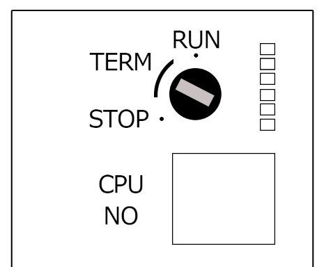
switch |
Setting contents |
MODE (Rotary Switch) |
TERM |
2.Start SX-Programme and create a new project
3.Open the menu "Online" - "Communication Settings" and confirm that you can communicate with PLC.
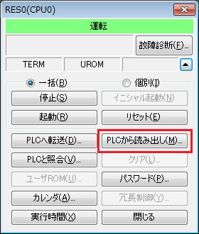
4.Open "Online" - "PLC Operation" from the menu, and select "Read from PLC" to read various unit information from PLC.
5.Select "System Definition" in the tree to display the System Definition dialog.
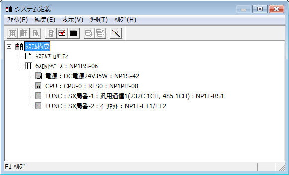
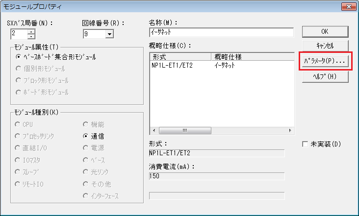
6.Select the Ethernet unit and view its properties
7.When the module properties appear, select the parameters
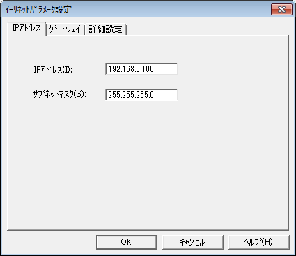
8.Set the Ethernet parameters as follows:
setting |
Setting contents |
IP address |
192.168.0.100 |
Subnet mask |
255.255.255.0 (set according to your environment) |
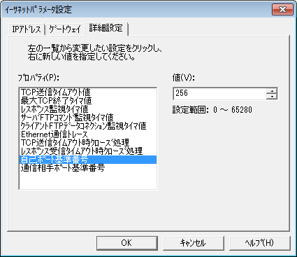
9.Open the Advanced Settings and set the value of Self Port Reference Number as follows:
Leave the other settings as default.
setting |
Setting contents |
value |
256 |
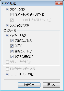
10.Press the OK button to close all dialogues, then select "Online" - "PLC Operation" from the menu and select "Transfer to PLC".
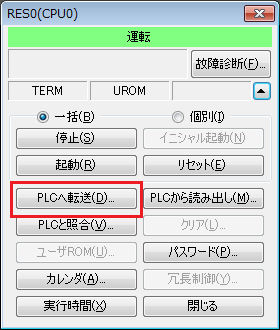
11.When the transfer dialog box appears, select "Program", "System definition", and "Module driver" and transfer them to PLC.
|
The port number on the PLC side (507) is the value obtained by adding 251 (fixed value) to the "Self-port reference number (default 256)" set in PLC. |
|
When writing values to a PLC, be sure to set the PLC mode to "TERM". Writing is not possible in "RUN" or "STOP". |
|
After setting the parameters, you must turn off the power to the PLC once to reflect the settings. Although a remote reset may be possible from the tool, we recommend turning off the power once to ensure that the settings are reflected. |
|
When transferring the module driver, if a connection other than the loader port, such as RS-232C, is used, a parameter error will occur and the transfer will fail, so please be careful. |
|
If the transfer fails when transferring a module driver, transfer the "program" and "system definition", reset the system, and then transfer only the module driver. |
PC settings
Use the Server application to connect to the PLC for which you have set up communications.
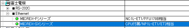
1.Right-click "Application" - "Driver" in the tree and select Add Driver.
2.Select the following units from the displayed driver list and add them:
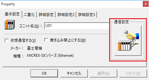
3.Open the properties of the added unit (U01) and click Communication Settings.
4.Configure the following in "PC Settings"
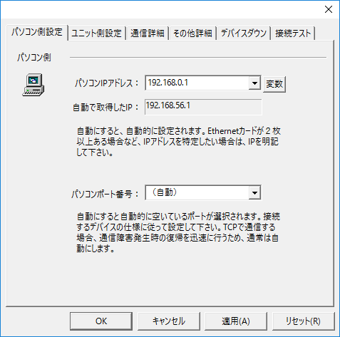
setting |
Setting contents |
Computer IP address |
192.168.0.1 |
Computer port number |
Automatic |
5.Set the following in "Unit side settings"
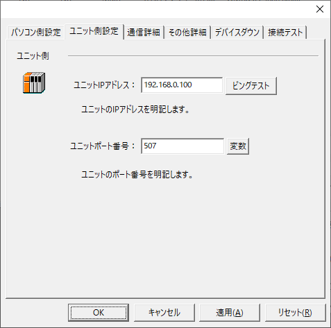
setting |
Setting contents |
Unit IP Address |
192.168.1.100 |
Unit Port Number |
507 |
6.Select "Ping Test" to check if the ping goes through normally.
If you see a message like "Ping test is success~", the test was successful.
7.Select the protocol in "Communication Details"
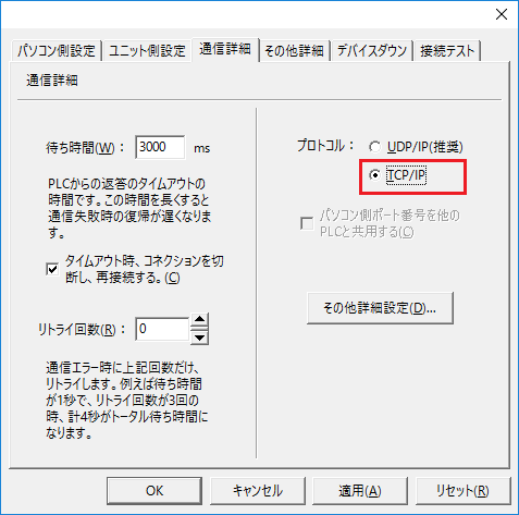
setting |
Setting contents |
protocol |
TCP/IP |
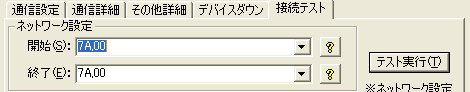
8.Perform a connection test to check the connection
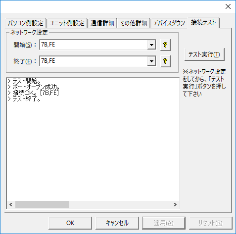
If a message such as "Connection OK" is displayed, the connection is confirmed to be OK.
|
During the connection test and in the "Network Settings" of the folder settings, specify the module to be transmitted. (Separate the connection method and connection ID with a comma. Usually, it is 7B,FE.)
|