overview
This is a setting example for connecting to the MICREX-F series via Ethernet.
Model used
item |
Model etc. |
PLC |
MICREX-F F120S |
Communication Unit |
NC1L-ET1 |
Configuration environment
item |
environment |
OS |
WindowsXP Professional 32Bit |
tool |
MICREX-F PLC Programmer Ver1.3.1.0 |
Configuration details
item |
setting |
Setting items |
Configuration Example |
PLC side settings |
Set with tools |
IP address |
192.168.1.100 |
Port number |
256 |
||
PC settings |
Unit Settings |
IP address |
192.168.1.1 |
Port number |
Automatic |
||
Communication Protocol |
TCP/IP |
* Most of the settings on the computer will be adjusted to match the settings on the unit.
PLC side settings
Configure the settings for "MICREX-F F120S" and "NC1L-ET1". The settings are configured using MICREX-F PLC Programmer.
1.Set the front switch of the "NC1L-ENT1" unit as follows:
switch |
NC1L-ET1 |
FFU170B |
Communication condition setting switch |
All OFF |
|
10Base2/T changeover switch |
T side |
- |
AUI/TPI Switch |
- |
TPI side |
10Base2/2 Switch |
- |
Either |
|
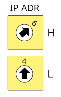
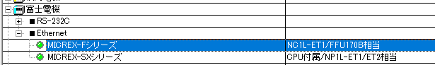
Specify the end of the IP address with the switch on the back. There are two switches, H and L, which are hexadecimal switches.
In this setting example, the last digit of the IP address is 100, which becomes "100" → "64" when converted to hexadecimal, so set H to "6" and L to "4". |
|
The end of the IP address is determined by the "IP address setting switch", not the ladder. |
|
The above example is the setting that works with "Ethernet User's Manual Chapter 7 Sample Program." In this connection example, TCP is selected as the protocol. Therefore, TCP must also be selected in the unit's communication settings. |
2.Set the rear switch of the "NC1L-ENT1" unit as follows:
3.Using MICREX-F PLC Programmer, refer to Fuji Electric's "Ethernet User's Manual, Chapter 7 Sample Program" and write the following ladder.
4.Write the ladder
5.Refer to Fuji Electric's "Ethernet User's Manual" and set the initial parameters and communication parameters to the address (tag) of the relevant device as follows.
tag |
Setting contents |
Setting Value |
W30.0 |
IP address (upper 2 digits of hexadecimal) |
C0A8 |
W30.1 |
IP address (lowest 2 digits in hexadecimal) However, the last two digits are set using a switch, so they must be 00 (xx00). |
0100 |
W30.21 |
Port number |
256 |
PC settings
Use the Server application to connect to the PLC for which you have set up communications.
1.Right-click "Application" - "Driver" in the tree and select Add Driver.
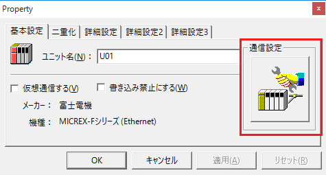
2.Select the following units from the displayed driver list and add them:
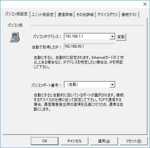
3.Open the properties of the added unit (U01) and click Communication Settings.
4.Configure the following in "PC Settings"
setting |
Setting contents |
Computer IP address |
192.168.1.1 |
Computer port number |
Automatic |
5.Set the following in "Unit side settings"
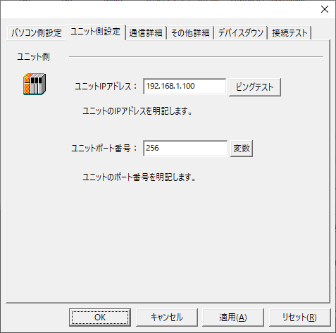
setting |
Setting contents |
Unit IP Address |
192.168.1.100 |
Unit Port Number |
256 |
6.Select "Ping Test" to check if the ping goes through normally.
If you see a message like "Ping test is success~", the test was successful.
7.Select the protocol in "Communication Details"
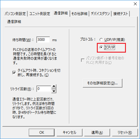
setting |
Setting contents |
protocol |
TCP/IP |
8.Perform a connection test to check the connection
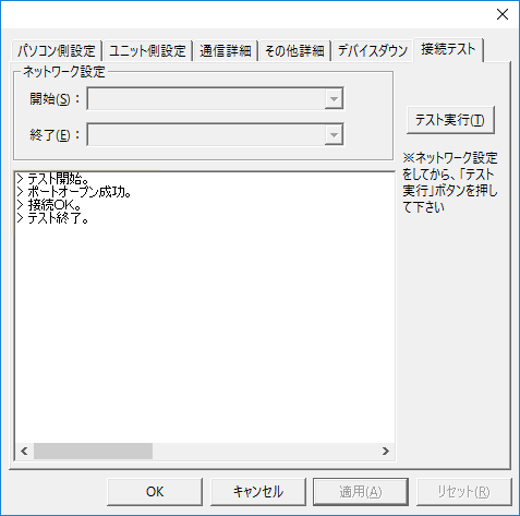
If a message such as "Connection OK" is displayed, the connection is confirmed to be OK.