overview
This is a setting example for connecting to the MICREX-SX series via RS-232C.
Model used
item |
Model etc. |
PLC |
MICREX-SX NP1PH-08 |
Communication Unit |
NP1L-RS2 |
Configuration environment
item |
environment |
OS |
WindowsXP Professional 32Bit |
Configuration details
item |
setting |
Setting items |
Configuration Example |
PLC side settings |
Set with switch |
MODE |
1 (loader) |
PC settings |
Unit Settings |
COMPort |
Communication port number to connect to |
Transmission speed |
38400bps |
||
Byte Size |
8bits |
||
Stop bits |
1bits |
||
parity |
Even |
||
Folder and communication test settings |
Connection method |
7B |
|
Connection ID |
FE |
* Most of the settings on the computer will be adjusted to match the settings on the unit.
|
When writing values to a PLC, be sure to set the PLC mode to "TERM". Writing is not possible in "RUN" or "STOP". |
|
When using a communication unit equivalent to PV1L-RS2, the communication specifications are fixed (transmission speed: 38400bps, byte size: 8 bits, stop bit: 1 bit, parity: even). Therefore, there are no setting items. |
|
Communication is also possible through the loader port attached to the CPU. The cable used with Fuji Electric's SX-Programmer(D300win can be used as is. There is no need to set up communication on the PLC side. The communication specifications are fixed (transmission speed: 38400bps, byte size: 8 bits, stop bit: 1 bit, parity: even). |
PLC side settings
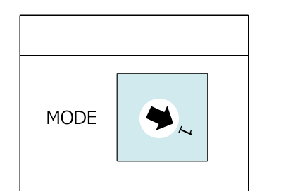
Set up the "NP1L-RS2" using the switch on the front.
1.Set the front switch as follows:
switch |
explanation |
Setting contents |
MODE (Rotary Switch) |
Transmission Mode |
1 (loader) |
|
For details on the switch settings, etc., please refer to Fuji Electric's "F55 Series General-Purpose Interface Card User Manual TYPE NV1L-RS2." |
PC settings
Use the Server application to connect to the PLC for which you have set up communications.
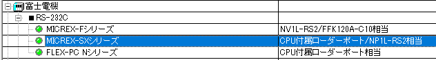
1.Right-click "Application" - "Driver" in the tree and select Add Driver.
2.Select the following units from the displayed driver list and add them:
3.Open the properties of the added unit (U01) and click Communication Settings.
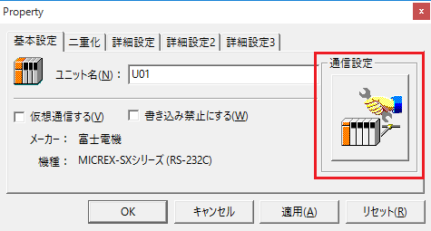
4.Set "Communication Settings" as follows:
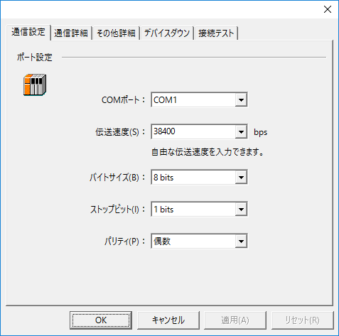
setting |
Setting contents |
COMPort |
Communication port number to connect to |
Transmission speed |
38400 |
Byte Size |
8bits |
Stop bits |
1bits |
parity |
Even |
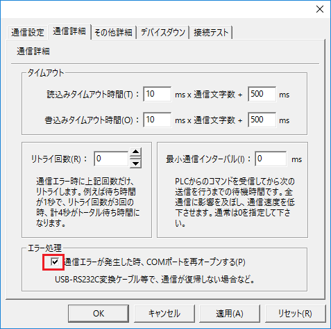
5.USB-RS-If you are using a 232C conversion cable, the COM port may be locked in the event of a communication error, so check the reopen setting.
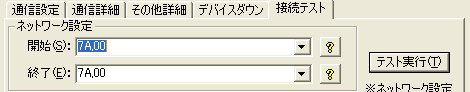
6.Perform a connection test to check the connection
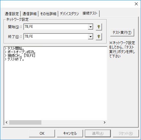
If a message such as "Connection OK" is displayed, the connection is confirmed to be OK.
|
During the connection test and in the "Network Settings" of the folder settings, specify the module to be transmitted. (Separate the connection method and connection ID with a comma. Usually, it is 7B,FE.)
|