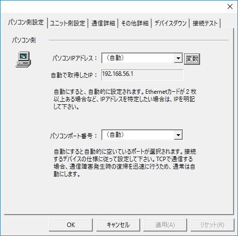
Computer settings
|
•Computer IP address
The IP address of your computer. If you select Automatic, a default IP address will be set.
•Computer port number
Port number on the computer side. If you set it to "Automatic", an available port will be selected.
If you want to communicate using TCP instead of UDP, set it to Automatic.
|
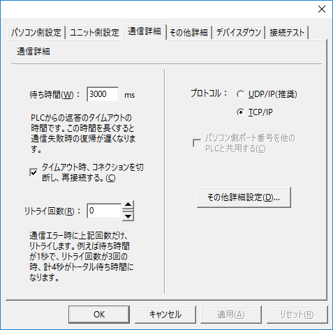
Communication details
|
•Waiting time
Response timeout from
PLC.
•Retry count
When a communication error occurs, the system will retry the specified number of times.
•protocol
Select
UDP or TCP.
For a
Modbus/TCP connection, be sure to select TCP/IP. |
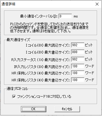
Other detailed settings
|
•Minimum Communication Interval
Specifies the waiting time on the PC side after receiving a device value from
PLC and before the next transmission.
•Maximum communication size
The maximum communication size is the maximum packet size per packet for each communication. If the maximum packet size of the connected Modbus-compatible device is small, errors may occur when reading or writing to a large area. In such cases, check the connected Modbus-compatible device and adjust the setting value.
In addition, our communication driver optimizes packets so that communication requests are as few as possible. For example, even if multiple tags have non-consecutive addresses set at random, communication requests are processed together within the size set by the maximum communication size. If for some reason you do not want to optimize packets, specify "-1" as the maximum communication size for the target address.

|
When connecting to a device with a scattered address map, even if you register only existing addresses in the tag and communicate, packet optimization will cause a communication request to be made for all addresses, including those that do not exist on the device. Depending on the specifications of the connected device, an error may be returned if a communication request is made to a non-existent Modbus address. In such cases, you can prevent packet optimization by setting the maximum communication size to "-1", and avoid errors. However, communication speed will be slower if packet optimization is not performed. For example, if 100 tags are defined, a total of 100 communications will be made for each folder update cycle.
|
•Communication Protocol
Regarding writing to
HR (holding register), for Modbus-compatible devices that do not support function code 16, uncheck "Supports function code 16." If not checked, writing to HR will be done using function code 6.
|