overview
This section explains how to connect to various OMRON devices via RS-232C.
Compatible models
List of compatible devices
Connection method |
Series/Model etc. |
Connection Unit |
Supported drivers |
RS232-C |
C/CV/CS1/CJ1/CJ2 Series (C mode) |
・C200H-LK101-PV1/201-V1/202-V1 ・C500-LK101-(P)V1/201-V1 ・C500-LK103-(P)/203 ・C120-LK101-(P)V1/201-V1/202-V1 ・Equivalent to LK-201 ・CPU accessory port
|
Omron-RS-232C C/CV/CS1/CJ1 Series (C mode)
[Connection protocol] C Mode |
CVM1/CV Series (FINS) |
・CPU accessory port ・CV500-LK-201 equivalent |
Omron-RS-232C CVM1/CV Series(FINS)
[Connection protocol] FINS |
|
CS1/CJ1 Series (FINS) |
・CPU accessory port ・CS1W-SCU21 equivalent
|
Omron-RS-232C CS1/CJ1 series (FINS)
[Connection protocol] FINS |
|
For combinations of CPU units and link units, please check with the device manufacturer to see if the model combination is actually possible. Also, please check whether communication is possible with the protocol used when connecting with our company for that combination. |
(Reference material) Model list
series |
Model etc. |
C Series |
C200HX, C200HG, C200HE etc. |
CV Series |
C500-PS222, CV500-PS221, CVN1 etc. |
CS1 Series |
CS1G-CPU42H, CS1G-CPU43H, CS1G-CPU44H, CS1G-CPU45H, CS1H-CPU63H, CS1H-CPU64H , CS1H-CPU65H, CS1H-CPU66H, CS1H-CPU67H, CS1D-CPU65H, CS1D-BC052, CS1D-BC082S, CS1D-BI092 etc. |
CJ1 Series |
CJ1G-CPU42P, CJ1G-CPU43P, CJ1G-CPU45P, CJ1M-CPU11, CJ1M-CPU12, CJ1M-CPU13, CJ1M-CPU21, CJ1M-CPU22, C J1M-CPU23, CJ1M-CPU11-ETN, CJ1M-CPU12-ETN, CJ1M-CPU13-ETN, CJ1M-CPU21, CJ1M-CPU22, CJ1M-CPU23 etc. |
CJ2 Series |
CJ2M-CPU11, CJ2M-CPU12, CJ2M-CPU13, CJ2M-CPU14, CJ2M-CPU15, CJ2M-C PU31, CJ2M-CPU32, CJ2M-CPU33, CJ2M-CPU34, CJ2M-CPU35, CJ2H-CPU64- EIP, CJ2H-CPU65-EIP, CJ2H-CPU66-EIP, J2H-CPU67-EIP, CJ2H-C PU68-EIP, CJ2H-CPU64, CJ2H-CPU65, CJ2H-CPU66, CJ2H-CPU67, CJ2H-CPU68 etc. |
CP1E Series |
CP1E-E10DR-A, CP1E-E10DR-D, CP1E-E10DT-A, CP1E-E10DT-D, CP1E-E14DR-A, CP1E-E14SDR-A, CP1E-E2 0DR-A, CP1E-E20SDR-A, CP1E-E30DR-A, CP1E-E30SDR-A, CP1E-E40DR-A, CP1E-E40SDR-A, CP1E-E60SDR- A, CP1E-N14DR-A, CP1E-N14DR-D, CP1E-N14DT-A, CP1E-N14DT-D, CP1E-N14DT1-D, CP1E-N20DR-A, CP1E- N20DR-D, CP1E-N20DT-A, CP1E-N20DT-D, CP1E-N20DT1-D, CP1E-N30DR-A, CP1E-N30DR-D, CP1E-N30DT-A, CP1E-N30DT-D, CP1E-N30S1DR-A, CP1E-N30S1DT-D, CP1E-N30SDR-A, CP1E-N30SDT-D, CP1E-N40DR-A, CP 1E-N40DR-D, CP1E-N40DT-A, CP1E-N40DT-D, CP1E-N40DT1-A, CP1E-N40S1DR-A, CP1E-N40S1DT-D, CP1E-N 40SDR-A, CP1E-N40SDT-D, CP1E-N60DR-A, CP1E-N60DR-D, CP1E-N60DT-A, CP1E-N60DT-D, CP1E-N60DT1- D, CP1E-N60S1DR-A, CP1E-N60S1DT-D, CP1E-N60SDR-A, CP1E-N60SDT-D, CP1E-NA20DR-A, CP1E-NA20DT-D etc. |
CP1L Series |
CP1L-EL20DR-D,CP1L-EL20DT-D,CP1L-EM30DR-D,CP1L-EM30DT-D,CP1L-EM40DR-D,CP1L-EM40DT-D,CP1L-L10DR-A,CP1L-L10DT-A,CP1L-L10DT1-D,CP1L-L14DR-A,CP1L-L14DR-D,CP1L-L14DT-A,CP1L-L14DT-D,CP1L-L14DT1-D,CP1L-L20DR-A,CP1L-L20DR-D,CP1L-L20DT-A,CP1L-L20DT-D,CP1L-L20DT1-D,CP1L-M30DR-A,CP1L-M30DR-D,CP1L-M30DT-A,CP1L-M30DT-D,CP1L-M40DR-A,CP1L-M40DR-D,CP1L-M40DT-A,CP1L-M40DT-D,CP1L-M60DR-A,CP1L-M60DR-D,P1L-M60DT-A,CP1L-M60DT-D,CP1L-M60DT1-D etc. |
CP1H Series |
CP1H-X40DR-A,CP1H-X40DT-D,CP1H-XA40DR-A,CP1H-XA40DT-D,CP1H-Y20DT-D etc. |
NJ Series |
NJ301-1100, NJ301-1200, NJ501-1300, NJ501-1400 etc. |
Settings Dialog Details
RS-232C common
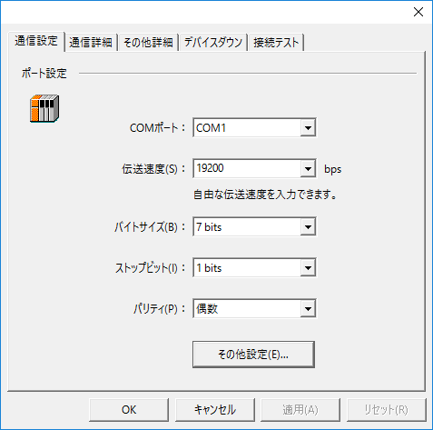
Communication Settings
|
•COMPort
•Transmission speed
•Byte Size
•Stop bits
•parity
|
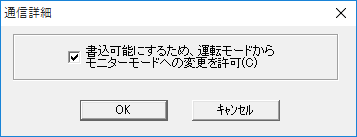
Other settings
|
•To make it writable, allow changes... |
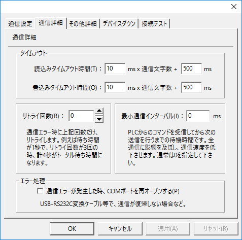
Communication details
|
•Read timeout setting
•Write timeout setting
•Retry count
•Minimum Communication Interval
•Error Handling |