overview
This is an example of Ethernet connection settings with the FP series.
Model used
item |
Model etc. |
PLC |
FP-10SH |
Communication Unit |
FP3 ET-LAN |
Configuration environment
item |
environment |
OS |
Windows7 Professional 64Bit |
tool |
FPWIN GR Ver2.9180.2 |
Configuration details
item |
setting |
Setting items |
Configuration Example |
PLC side settings |
Setting with switches and tools |
IP address |
192.168.0.100 |
Port number |
4097 |
||
PC settings |
Unit Settings |
IP address |
192.168.0.1 |
Port number |
Automatic |
||
Communication Protocol |
TCP/IP |
||
Folder and communication test settings |
Target station number (decimal) |
00 |
|
Relay station 1 number (decimal) |
00 |
||
Relay station 1 route number (decimal) |
00 |
||
Relay station 2 number (decimal) |
00 |
||
Relay station 2 route number (decimal) |
00 |
||
Relay station 3 number (decimal) |
00 |
||
Relay Station 3 Route No. (Decimal) |
00 |
* Most of the settings on the computer will be adjusted to match the settings on the unit.
PLC side settings
Set up "FP3 ET-LAN". Settings are made using the front switch and FPWIN GR, etc.
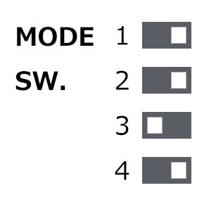
1.Set the switch as follows:
|
|
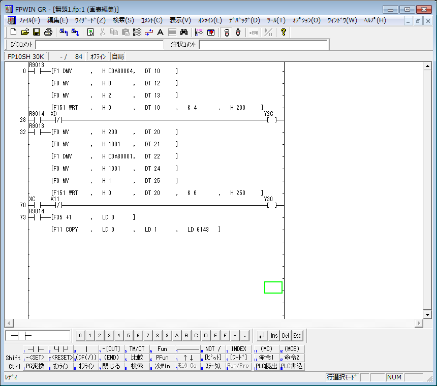
2.FPWIN Setting ladder in GR
For "FP3 ET-LAN", the IP address and other settings must be initialized in the ladder program. Please create the following ladder.
The following program is based on the program published in the "MEWNET FP3 ET-LAN Unit Introduction Manual" published by Panasonic.
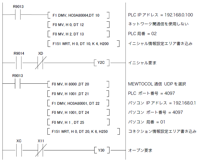
* Each IP address and port number is set in hexadecimal.
※1 This is the IP address of PLC. Please set it in hexadecimal. Example) 192.168.0.100 → C0A80064
※4 PLC port number. Please set it in hexadecimal. Example) 4097 (decimal) → 1001 (hexadecimal)
※5 This is the IP address of the computer. Please set it in hexadecimal. Example) 192.168.0.1 → C0A80001
※6 This is the computer's port number. Please set it in hexadecimal. Example: 4097 (decimal) → 1001 (hexadecimal)
3.After creating the ladder, write it to PLC by clicking the Download to PLC button.
PC settings
Use the Server application to connect to the PLC for which you have set up communications.
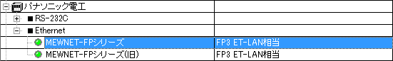
1.Right-click "Application" - "Driver" in the tree and select Add Driver.
2.Select the following units from the displayed driver list and add them:
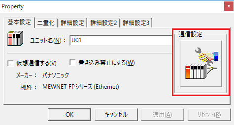
3.Open the properties of the added unit (U01) and click Communication Settings.
4.Configure the following in "PC Settings"
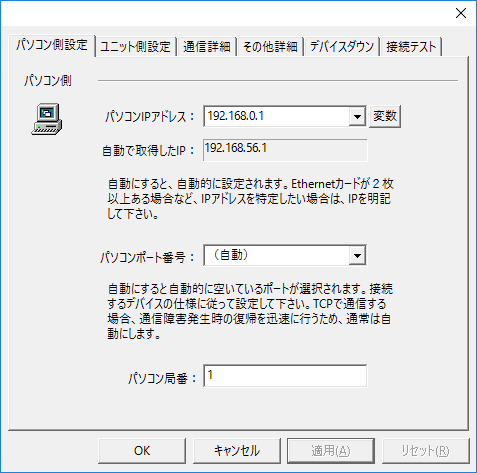
setting |
Setting contents |
Computer IP address |
192.168.0.1 |
Computer port number |
Automatic (Select Automatic because it is a TCP connection. 4097 is also acceptable.) |
Computer area code |
1 |
5.Set the following in "Unit side settings"
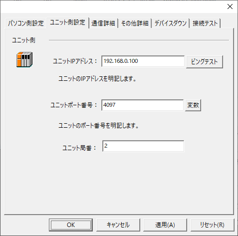
setting |
Setting contents |
Unit IP Address |
192.168.0.100 |
Unit Port Number |
4097 (specified in decimal) |
Unit Station Number |
2 |
6.Select "Ping Test" to check if the ping goes through normally.
If you see a message like "Ping test is success~", the test was successful.
7.Select the protocol in "Communication Details"
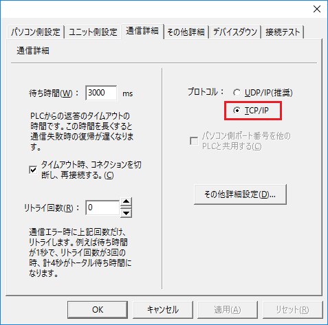
setting |
Setting contents |
protocol |
TCP/IP |
8.Perform a connection test to check the connection
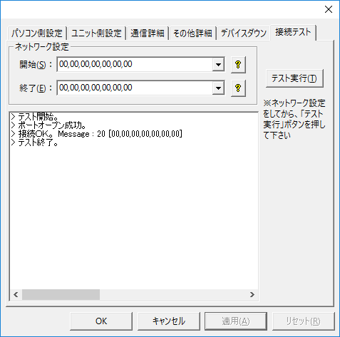
If a message such as "Connection OK" is displayed, the connection is confirmed to be OK.