overview
This is a setting example for connecting to the JW series via Ethernet.
Model used
item |
Model etc. |
PLC |
JW-22CU |
Communication Unit |
JW-255CM |
Configuration environment
item |
environment |
OS |
Windows7 Professional 64Bit |
tool |
JW300SP V3.8 |
Configuration details
item |
Setting items |
Configuration Example |
PLC side settings |
IP address |
192.168.0.100 |
Subnet mask |
255.255.255.0 |
|
Port number |
8192 |
|
Communication Protocol |
UDP |
|
PC settings |
IP address |
192.168.0.1 |
Port number |
Automatic |
|
Communication Protocol |
UDP |
* Most of the settings on the computer will be adjusted to match the settings on the unit.
PLC side settings
Set it to "JW-255CM". Settings are made using the front switch and JW300SP, etc.
1.Connect the Programmer port of the "JW-255CM" to the computer using a dedicated cable.
2.Start JW300SP and create a new project.
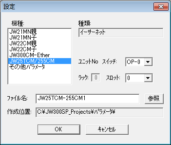
3.Select "Optional parameters" from the tree and open the settings screen.
4.Select "Create New", open the settings screen, and select the unit you want to use.
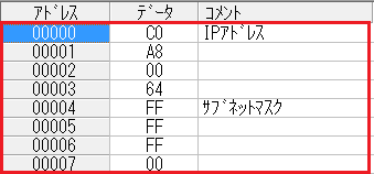
5.Set the network parameters as follows:
address |
Contents |
Setting value (hexadecimal) |
0000 |
Setting the PLC IP address (192.168.0.100) |
C0 |
0001 |
A8 |
|
0002 |
00 |
|
0003 |
64 |
|
0004 |
Set the subnet mask (255.255.255.0) |
FF |
0005 |
FF |
|
0006 |
FF |
|
0007 |
00 |
|
... |
... |
... |
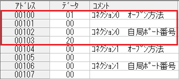
0100 |
Using UDP |
01 |
0101 |
00 |
|
0102 |
Port number setting (8192) |
00 |
0103 |
20 |
6.Select "PLC" - "Run/Stop" from the menu and stop the CPU operation.
7.Select "PLC" - "PLC Transfer" - "Write" from the menu and write the parameters.
8.Select "PLC" - "Operation Settings" - "Write to EEPROM and start operation" from the menu and write to EEPROM.
9.Select "PLC" - "Run/Stop" from the menu and start running the CPU.
|
When setting parameters for the "KJW-255CM", you must connect the cable directly to the communication unit. Please note that if you connect to the port attached to the KCPU, you will not be able to set parameters for the communication unit. |
PC settings
Use the Server application to connect to the PLC for which you have set up communications.
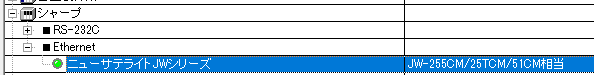
1.Right-click "Application" - "Driver" in the tree and select Add Driver.
2.Select the following units from the displayed driver list and add them:
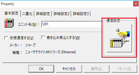
3.Open the properties of the added unit (U01) and click Communication Settings.
4.Configure the following in "PC Settings"
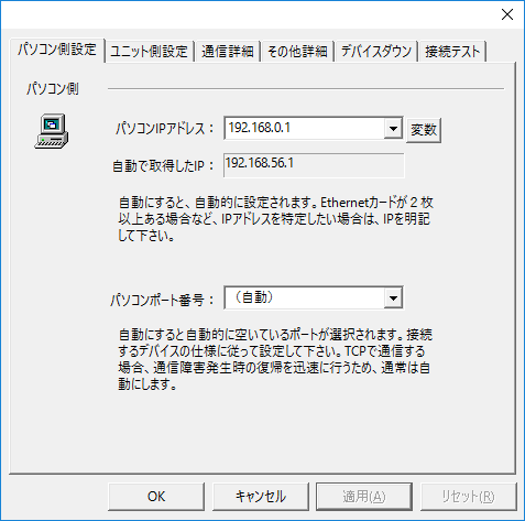
setting |
Setting contents |
Computer IP address |
192.168.0.1 |
Computer port number |
Automatic |
5.Set the following in "Unit side settings"
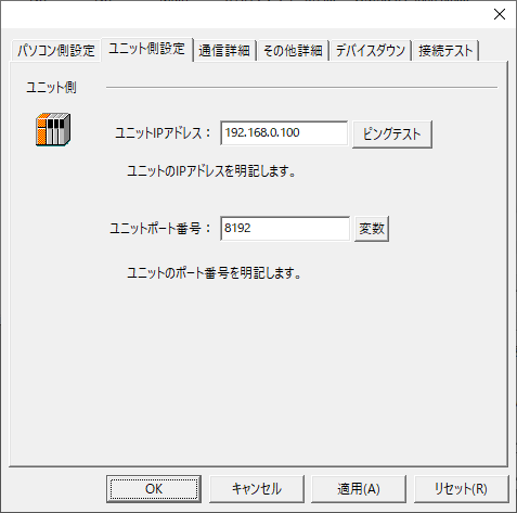
setting |
Setting contents |
Unit IP Address |
192.168.0.100 |
Unit Port Number |
8192 |
6.Select "Ping Test" to check if the ping goes through normally.
If you see a message like "Ping test is success~", the test was successful.
7.Select the protocol in "Communication Details"
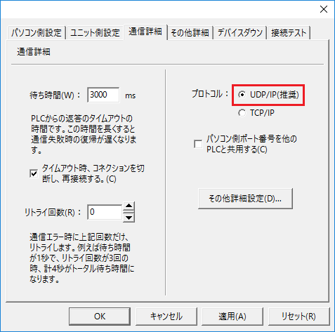
setting |
Setting contents |
protocol |
UDP (recommended) |
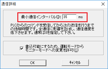
8.Adjust the minimum communication interval from 35m in 5ms increments to suit the connected CPU.
|
Minimum communication interval
Among the JW series PLCs, there are some models that require a certain amount of time to pass after the PC receives a command from the PLC before it can send a command to PLC. If you are using a model with this restriction and you are experiencing intermittent timeout errors, try increasing the [Minimum communication interval] setting in 5 ms increments.
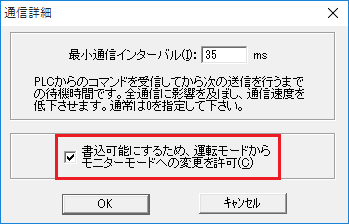
The [Minimum communication interval] setting can be changed in the dialog that appears by clicking the "Other detailed settings" button on the "Communication details" tab in the "Communication settings" dialog. |
9.Check the following settings:
10.Perform a connection test to check the connection
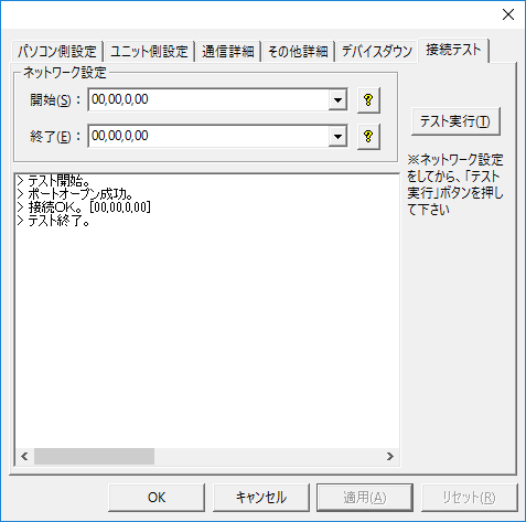
If a message such as "Connection OK" is displayed, the connection is confirmed to be OK.