overview
This is a configuration example for connecting to WAGO 750-842 via Ethernet.
Model used
item |
Model etc. |
device |
750-842 |
Communication Unit |
Ports included with the unit |
Configuration environment
item |
environment |
OS |
WindowsXP 32Bit |
tool |
WAGO BootP Server Ver1.0.0 |
Configuration details
item |
setting |
Setting items |
Configuration Example |
PLC side settings |
Set with tools |
IP address |
192.168.0.100 |
Port number |
502 |
||
PC settings |
Unit Settings |
IP address |
192.168.0.1 |
Port number |
Automatic |
* Most of the settings on the computer will be adjusted to match the settings on the unit.
PLC side settings
Set it to "750-842". The setting is done by WAGO BootP Server.
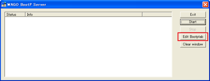
1.Start WAGO BootP Server and press the "Edit Bootptab" button.
2.A text file with the configuration information will be displayed, so you can enter the main settings such as the IP address.
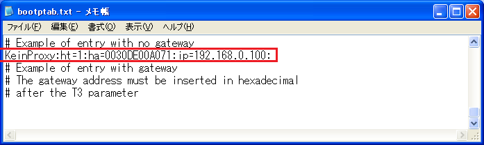
Here, only the MAC address and IP address are set. The settings are, from left to right,Node Name",Hardware Type",MAC address",IP addressAfter you have set the file, save it. After saving, you can close the text file.
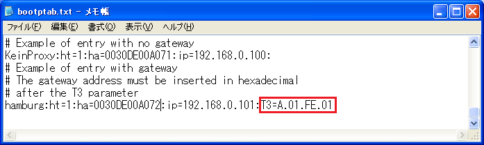
If you are using a
gateway, useT3=Specify the gateway address after "." Note that in this connection example, a gateway is not used, so this line is not included.
Also, to set the netmask (sm) and default gateway (gw), enter them after the IP address as follows:
KeinProxy:ht=1:ha=xxxxxxxxxxxx:ip=xxx.xxx.xxx.xxx:sm=255.255.255.0:gw=10.1.254.1
For more information, please refer to the WAGO BootP Server manual.
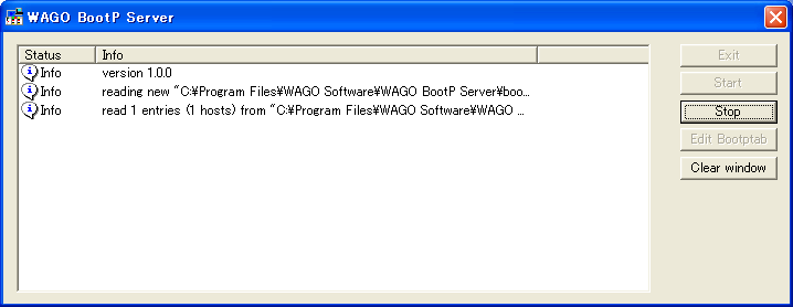
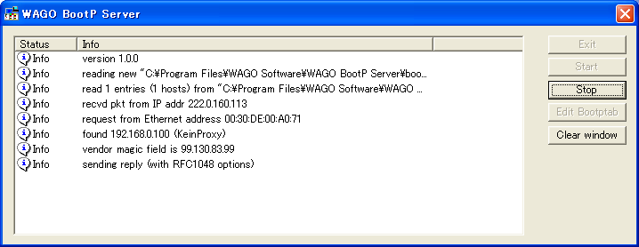
3.Press the "Start" button
The following three lines of log will be displayed, so power on the node now.
4.When you turn the power on, the node name and IP address you set will be displayed.
If you need to restart the device, please wait 2 seconds after turning the power off before restarting the device.
5.Press "Stop" to exit the tool
PC settings
Use the Server application to connect to the PLC for which you have set up communications.
1.Right-click "Application" - "Driver" in the tree and select Add Driver.
2.Select the following units from the displayed driver list and add them:

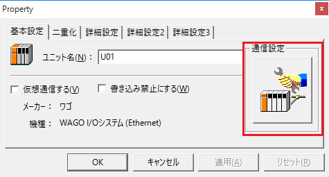
3.Open the properties of the added unit (U01) and click Communication Settings.
4.Configure the following in "PC Settings"
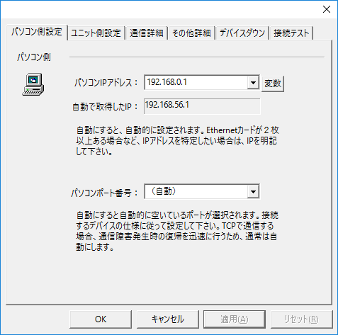
setting |
Setting contents |
Computer IP address |
192.168.0.1 |
Computer port number |
Automatic |
|
Since it is not possible to specify the port number of the connection destination on the PLC side, please set the port number on your computer to "Automatic." |
5.Set the following in "Unit side settings"
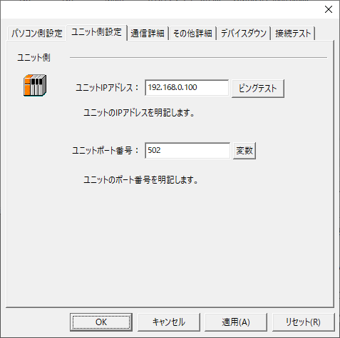
setting |
Setting contents |
Unit IP Address |
192.168.0.100 |
Unit Port Number |
502 |
6.Select "Ping Test" to check if the ping goes through normally.
If you see a message like "Ping test is success~", the test was successful.
7.Perform a connection test to check the connection
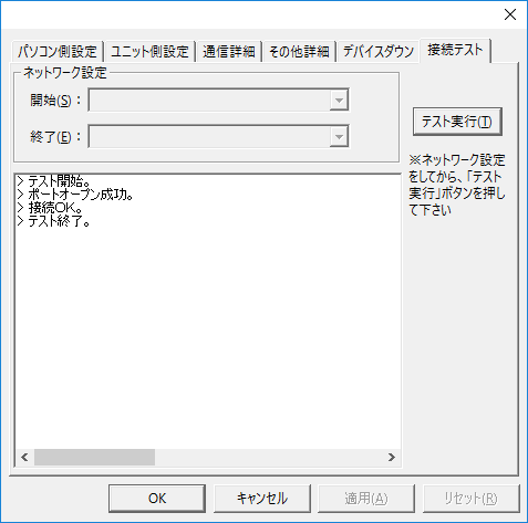
If a message such as "Connection OK" is displayed, the connection is confirmed to be OK.