overview
This article explains how to connect to Yokogawa Electric devices via RS-232C.
Compatible models
List of compatible devices
Connection method |
Series/Model etc. |
Connection Unit |
Supported drivers |
RS232-C |
FA-M3 Series |
・F3LC11-1F ・F3LC11-2F ・F3LC12-1F ・F3LC21-1N ・Equivalent to F3LC11-1N |
Yokogawa Electric - RS-232C FA-M3
[Connection protocol] PC Link |
|
For combinations of CPU units and link units, please check with the device manufacturer to see if the model combination is actually possible. Also, please check whether communication is possible with the protocol used when connecting with our company for that combination. |
(Reference material) Model list
series |
Model etc. |
FA-M3 Series |
F3SP71-4S, F3SP76-7S, F3SP66-4S, F3SP67-6S, F3SP21-0N, F3SP25-2N, F3SP35-5N, F3SP20-0N, F3SP30-0N , F3SP28-3N, F3SP38-6N, F3SP53-4H, F3SP58-6H, F3FP36-3N, F3SP71-4N, F3SP76-7N, F3SP28-3S, F3SP38-6S , F3SP53-4S, F3SP58-6S, F3SP59-7S, F3SP22-0S, F3SP71-4S, F3SP76-7S, F3SP22-0S, F3SP71-4S, F3SP71-4S , F3SP76-7S, F3SP71-4S, F3SP76-7S, F3SP71-4S, F3SP76-7S, F3SP71-4S, F3SP76-7S, F3SP71-4S, F3SP76-7S etc. |
Accessing the common area of the BASIC and CPU modules
To access the common area of a BASIC CPU module (such as F3BP20), specify as follows:
Common area word access
Specify the device as "Dxxxx". "D0001" indicates the beginning of the common area, and one device is one word. For integer type tags, one device is assigned to one tag.
Common area bit access
Specify the device as "Ixxxx". "I0001" indicates the beginning of the common area, and 1 device is 1 bit. For integer type tags, 16 devices are assigned to one tag.
Settings Dialog Details
RS-232C common
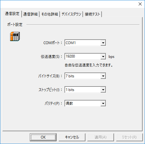
Communication Settings
|
•COMPort
•Transmission speed
•Byte Size
•Stop bits
•parity
|
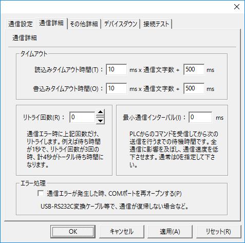
Communication details
|
•Read timeout setting
•Write timeout setting
•Retry count
•Minimum Communication Interval
•Error Handling |