Monitoring system development workflow
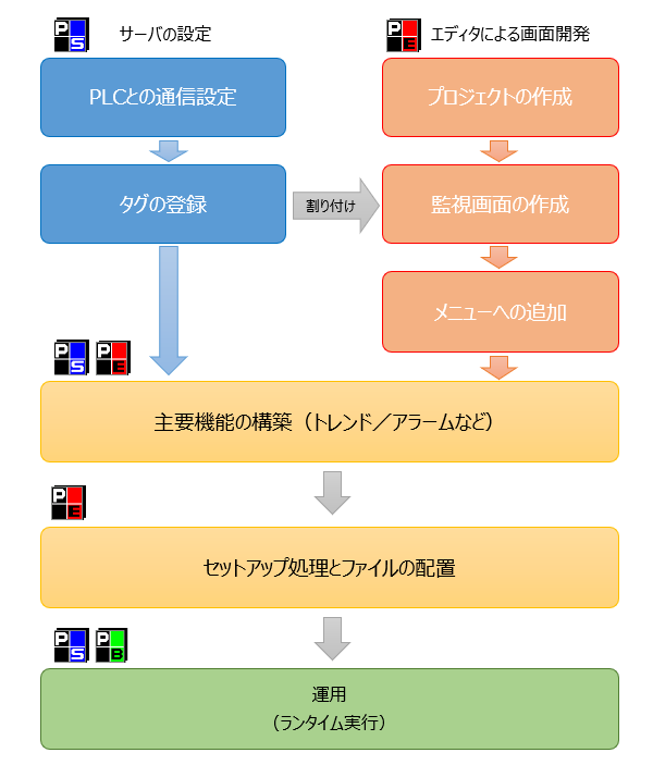
Developing a monitoring system using FA-Panel can be divided into screen development using an editor (creating screens using Panel Editor) and server-side configuration work (tag settings and various settings on Panel Server).
The diagram below shows the development work flow.
Screen development using an editor
When developing using the client screen editor (Panel Editor), you will mainly perform the following tasks:
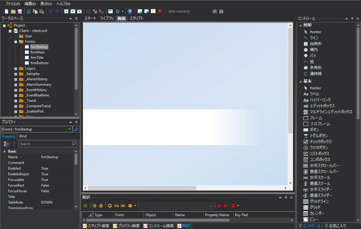
■ Creating a project
Use Panel Editor to create a "project." A "project" is the monitoring system itself developed with FA-Panel, and the "client configuration file" that saves the screens created with Panel Editor and the "server configuration file" created with Panel Server can be managed together as a project.
Furthermore, by creating a new project using the "Frame Library" function, you can easily create a skeleton project (standard project) that contains all the main functions required for a surveillance system.
■ Creating a monitoring screen
Graphic screens are drawn using Panel Editor. In the world of FA-Panel, screens are called "forms" and screen display is done on a form-by-form basis. These are divided into display screen units required for the monitoring system and created. Graphic displays on the screen are created by pasting parts called "parts libraries" and the smallest parts called "controls" such as labels/lines/rectangles/ellipses onto forms and setting "tags" (for example, turning on/off the PLC signal to turn on the lamp display of a part red/green, etc.).
■ Creating call processes for each screen
Create a mechanism to call up the monitoring screen form created above (add it to the menu, place a screen call button, etc.).
Server Configuration
The configuration work on the server side (Panel Server) mainly involves the following tasks:
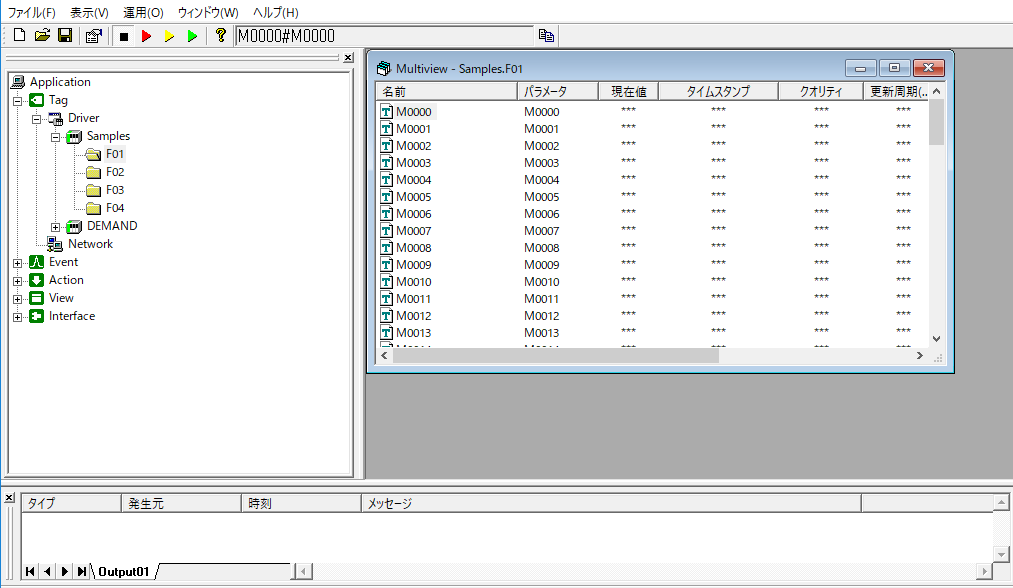
■ Communication settings with PLC
Communication settings with PLC are made in units called "units." One unit corresponds to one PLC, and multiple units can be configured at the same time. Information about the PLC to be connected (network identification, PLC address, etc.) is set for this unit.
■ Tag registration
After registering a unit, register a "tag" to the unit. The tag is used to send and receive signals between FA-Panel and PLC. Define which device address on PLC the registered tag corresponds to.
Building the main features
If necessary, configure various major functions required for the system you are building.
Specifically, the following standard functions will be configured:
•Configuring Logging
•Trend screen settings
•Registering alarm monitoring targets
•Daily report summary settings and layout definition
Setup process and file placement
Once you have finished your development work, perform the setup process in Panel Editor.
Place the distribution files generated by the setup on the actual PC in the production environment.
System operation (runtime execution)
When the system is operational, the server and the client run at runtime.
■ Server runtime execution
Runtime execution of the server is performed on Panel Server. (Panel Server is executed in runtime mode (online).)
■ Client runtime execution
The client's runtime execution is done in Panel Browser. By opening the "client configuration file" of the screen created in Panel Editor in Panel Browser, the graphic screen created during development will be displayed.