overview
This is an example of setting up an Ethernet connection to Logix5550.
Model used
item |
Model etc. |
PLC |
Logix5571 |
Communication Unit |
1756-ENET |
Configuration environment
item |
environment |
OS |
Windows7 Professional 64Bit |
tool |
BOOTP/DHCP Server 2.3 |
RSLinx Classic Lite Rev3.51.01 CPR 9 SR 5.1 |
|
Studio5000 Var21.00 |
Configuration details
item |
setting |
Setting items |
Configuration Example |
PLC side settings |
Set with tools |
IP address |
192.168.0.100 |
Port number |
44818 (fixed) |
||
PC settings |
Unit Settings |
IP address |
192.168.0.1 |
Port number |
Automatic |
||
Folder and communication test settings |
SlotNo |
00 |
|
PortNo |
01 |
* Most of the settings on the computer will be adjusted to match the settings on the unit.
|
"BOOTP/DHCP Server" can be installed during the Studio5000 installation, but it can also be downloaded free of charge from the Rockwell Automation knowledge base. |
PLC communication settings
The IP address and other settings for PLC are set using "Studio5000", "RSLinx", "BOOTP/DHCP", etc. If an IP address has already been set, it is not necessary to set it in BOOTP/DHCP. In addition, when using each tool, it is recommended that you "run as administrator".
1.Connect directly to the PLC Ethernet unit with a LAN cable and start BOOTP/DHCP.
2.After startup, a list of devices that do not have IP addresses set is displayed at regular intervals.

3.Double-click the target device to display the setting screen and set a temporary IP address.
Please identify the target device by its MAC address.

setting |
Setting contents |
IP Addres |
192.168.0.100 |
4.If the settings are successful, the settings you made will be displayed in "Relation List".

5.Select the added setting and enable it from "Disable BOOTP/DHCP".

6.Issue a PING command from the command prompt to check that the IP address has been set correctly.
7.Start RSLinx
8.Click "Configure drivers"

9.From the connection driver selection screen, select "Ethernet/IP Driver". After selecting, click "Add New".

10.Set the name of the driver to be added.
Please specify any name according to your situation. Here, the default name is specified.

11.Select the Ethernet adapter on the computer you are using and click "OK".

12.When the added driver is displayed, close the dialog with the "Close" button.

13.Click on "RS Who"

14.After expanding the added adapter from the tree, select the Ethernet unit and select "Module Configuration" from the right-click menu.

15.Select the "Port Configuration" tab from the settings screen and perform the following settings.
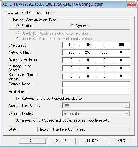
setting |
Setting contents |
Network Configuration Type |
Static |
IP Address |
192.168.0.100 |
Neteork Mask |
255.255.255.0 |
*Please set other settings such as "Gateway Address" according to your environment.
16.After completing the settings, click "OK".
Tag settings on PLC side
To check the connection, set a tag on the PLC side. If you do not need to perform a tag communication test, the following settings are not necessary.
1.Start Studio 5000
2.Start a new project from the Create item "New Project"

3.Select the controller you want to use, and set the project name and save location. After setting, click "Next".

4.Configure other settings such as chassis according to your environment, and click "Finish" after completing the settings.

5.Select "Controller setting" - "Controller Tags" in the tree and select "New Tag..." from the right-click menu.

6.Set the following two tags for testing:


Name |
DataType |
TAG_REAL |
REAL |
TAG_STRING |
STRING |
7.After setting up the tag, select "Communications" - "Who Active" from the menu.
8.Select the CPU unit and click "Download" to reflect the settings.

Communication settings on the computer
Use the Server application to connect to the PLC for which you have set up communications.
1.Right-click "Application" - "Driver" in the tree and select Add Driver.
2.Select the following units from the displayed driver list and add them:

3.Open the properties of the added unit (U01) and click Communication Settings.

4.Configure the following in "PC Settings"

setting |
Setting contents |
Computer IP address |
192.168.0.1 |
Computer port number |
Automatic |
5.Set the following in "Unit side settings"

setting |
Setting contents |
Unit IP Address |
192.168.0.100 |
Unit Port Number |
44818 (fixed) |
6.Select "Ping Test" to check if the ping goes through normally.
If you see a message like "Ping test is success~", the test was successful.
7.Perform a connection test to check the connection

If a message such as "Connection OK" is displayed, the connection is confirmed to be OK.
Tag settings on the computer
Set the tag to check the connection. If you do not need to perform a tag communication test, the following checks are not necessary.
1.Add a folder under a unit

2.Add the following tag:
■REAL type


■STRING type


Tag Name |
Tag communication parameters |
T01 |
TAG_REAL |
T02 |
TAG_STRING |
3.Start online communication
![]()
4.Verify that you can read and write tags
■ Server Application side

■Studio 5000 side
