overview
The following items are described as common device connection contents.
•Features of communication drivers
•Precautions when writing to a device
With this package, you can communicate with multiple PLCs of different models simultaneously with one license.
The following is the device driver selection screen.
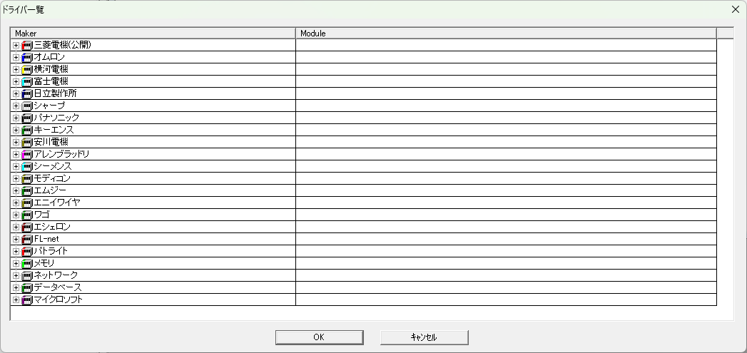
|
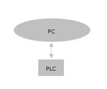
This is when connecting to one PLC. |
|
|
|
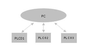
When connecting to multiple PLCs, communication with each PLC is independent and occurs in parallel. Even if one PLC becomes unable to communicate, it will not affect communication with the other PLCs. |
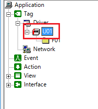
Communication settings with PLC are done in the following two places.
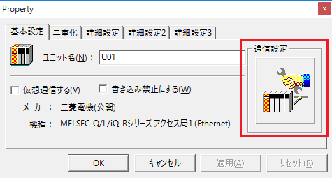
■ Unit Configure the connection settings specific to each PLC.
|
|
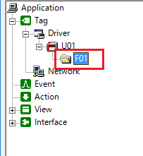
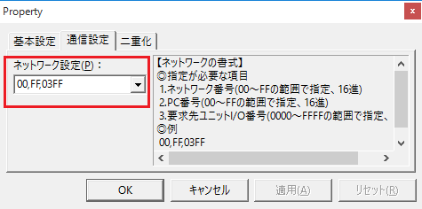
■ Folder Configure the network-related settings specific to each PLC. Please configure according to the "Network Format" displayed on the right.
|
|
|
When PLCs are connected in a multi-drop connection with RS-422 or in a manufacturer-specific network (such as MELSECNET), the different PLCs on the PLC specific network can be distinguished by folder by using the folder's "Network Settings." |
To perform a connection test, open the unit's communication settings and go to the "Connection Test" tab.
Example: Mitsubishi Q Series Ethernet
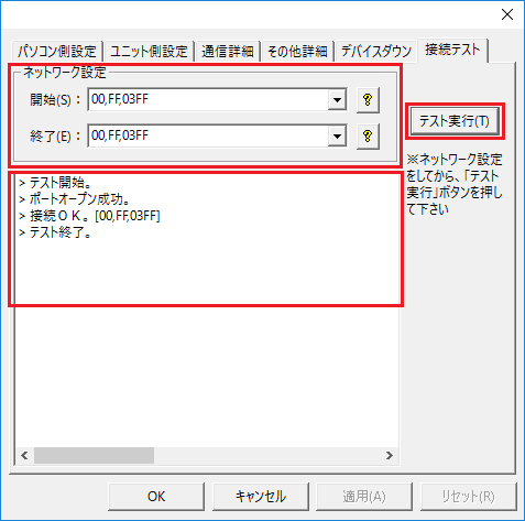
The unit's connection settings always have a "Connection Test" tab, where you configure the network settings and start the test by clicking the "Run Test" button.
Network Start and End performs sequential tests on multiple PLCs on the network.
If you are testing only one device, set the start and end times to the same.
When you run a test, the test results will be displayed. If the connection is not successful, please check the error message.
If communication with the connected PLC is lost, the unit's status will change to Device Down. Therefore, if the status is Device Down, it can be determined that an error has occurred in the communication or on the PLC side.
The device down setting is done in the Device Down item of the Communication Settings.
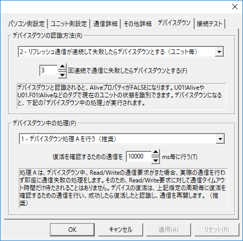
How to detect when a device is down
Select from the following three methods to detect when a device is down.
▪"Does not recognize device as down under any circumstances"
Select this setting if you do not want to recognize that the device is down. In this case, the system property Alive cannot detect that the device is down.
▪"If refresh communication fails consecutively, the device will be considered down (per folder/per unit)."
If communication with the unit fails the specified number of times, the device will be down. This setting can be selected for each folder or for each unit. If each folder is connected to a different PLC, set it for each folder. In other cases, set it for each unit.
The number of times can be changed by changing the following value. The default is 3 times.
![]()
|
If each folder is connected to a different PLC and you select each unit, if one of the folders experiences a device down state, the other folders will also experience a device down state. Therefore, you will not be able to communicate with PLCs that are not experiencing any abnormalities, so you will need to select each folder.
|
|
The number of seconds before the device goes down may depend on the wait time and number of retries set in the unit's advanced settings. for example,
・Communication tags are updated every second Waiting time: 3 seconds Number of retries: 3 - Number of communication failures: 3
In this case, the device will be recognized as down after 12 seconds (four 3-second retries) x 3, or approximately 36 seconds. |
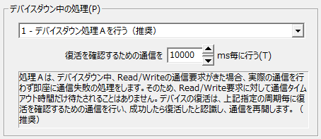
Processing when the device is down
Select from the following three options for processing after transitioning to device down.
▪"Do nothing even if the device goes down"
Select this only if you want to recognize device down information in the system property Alive. In other cases, do not select this.
▪"Perform device down processing A (recommended)"
This setting is selected by default.
When the device is down and a Read/Write communication request is received, this setting will not actually communicate and will immediately recognize the communication as having failed. Therefore, there will be no waiting timeout period for the Read/Write request.
The device will be checked for recovery at the specified interval, and communication will resume if the recovery check is successful.
▪"Perform device down process B"
To recover from a down device, a recovery check is performed at the specified interval, just like in process A, and if the recovery check is successful, communication is resumed.
If a Read/Write communication request is received in accordance with this cycle, communication will actually occur. If the communication is successful, the device down state will be lifted, so select this if you want to resume communication immediately.
|
The number of seconds before the device goes down may depend on the wait time and number of retries set in the unit's advanced settings. for example,
・Communication tags are updated every second Waiting time: 3 seconds Number of retries: 3 - Number of communication failures: 3
In this case, the device will be recognized as down after 12 seconds (four 3-second retries) x 3, or approximately 36 seconds. |
|
Unless you have a special reason, select the default action A, as it is the recommended option. |
|
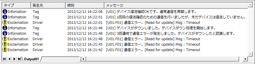
All information such as communication errors, recovery confirmation, and whether recovery is confirmed OK can be output to the Output Log.
|
The protocols for communicating with PLC vary depending on the manufacturer. Most PLCs have protocols for reading and writing data in bits or words. This package uses these protocols and is optimized internally to communicate at the highest speed.
Depending on the manufacturer's protocol specifications, you may need to be careful when writing. This can be a problem that occurs when writing in bit units to a device that does not support a bit-by-bit communication protocol.
For example, there are cases where a manufacturer's specific specifications only provide a communication protocol for a set unit such as a word.
If you want to read it bit by bit, you can simply read it word by word and extract the corresponding bits.
However, since writing can only be done in units of words, if you want to change only a portion of the corresponding bits, you must use a method that does not affect the other bits.
There are three possible ways to achieve this:
▪Level 1
The value from the previous communication is remembered, and only the corresponding bit is rewritten when writing.
However, "last time" here could be 100 ms ago, or it could be 1 minute ago. Therefore, if the PLC has changed the value in the meantime, the PC cannot detect the change, so if it rewrites it with the previous value, it may rewrite the part changed by the PLC back to the original value.
This is the simplest method if you are sure that
PLC will not rewrite the value.
▪Level 2
The current PLC value is obtained immediately before writing, and then immediately after obtaining the value, only the bit portion that you want to change is replaced with a new value and written.
This method has the disadvantage that communication occurs twice, but because the value immediately before writing (effectively about 20 to 60 ms before) is always used, a reliable value can be written unless the PLC changes the value within this tens of ms. This is the most common method.
▪Level 3
If stricter control is required, the Level 2 method may still cause problems. To completely prevent problems from occurring, you must devise a PLC ladder program.
There are two possible ways to do this.
One method is to indirectly control a device that can only be written to on a word-by-word basis by using a PC to rewrite the device, rather than directly rewriting the device from the PC. This can be achieved by indirectly preparing a device that the PLC will never be able to change, or a device that supports writing on a bit-by-bit basis, and then rewriting that device.
Another method is to use a "handshake flag." An arbitrary bit device is prepared as a handshake flag between the PC and PLC, and PLC notifies the PC whether writing is possible or not by turning that bit On/Off. The PC monitors the value of the flag through periodic communication, and writes to the PLC only when it is On. On the PLC side, logic is set up to guarantee that when the handshake flag is On, it will not rewrite values (values within word units) near the device to which the PC is writing.
Specifically, a tag (handshake flag) that performs cyclic communication is created and constantly monitored, and when it is confirmed that the bit is On, the necessary writing is performed. When writing is completed, the PC turns Off the handshake flag and notifies the PLC that writing is completed.
In this package, for devices that only support word-based writing in each manufacturer's protocol specifications, when writing to only some of the bits in a word, the "Level 2" processing is performed internally.
When performing "Level 3" control, the PLC ladder program is also involved, so the control level should be selected at the user's discretion.
However, if the manufacturer supports bit-wise communication, this will not be an issue since this package writes in bit units.
▪Summary of this matter |