overview
In this article, we will explain how to connect to FL-net.
Compatible models
List of compatible devices
Connection method |
Series/Model etc. |
Connection Unit |
Supported drivers |
FL-net |
CenturySystems |
・FL-PCI |
FL-Net-FL-PCI CenturySystems
[Connection protocol] FL-net
|
This package has been tested with the following firmware.
board |
Connection Protocol |
firmware |
FutureNet FL-PCI/V2 |
FL-net (OPCN-2 ver.1) |
49 |
FL-net (OPCN-2 ver.2) |
1006 |
|
FutureNet FL-PCI/V2-100 |
FL-net (OPCN-2 ver.2) |
2006 |
FutureNet FL-PCI/V2-100L |
FL-net (OPCN-2 ver.2) |
2007 |
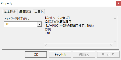
About node settings
Communication Settings
|
The communication node is specified in the folder settings. The folder settings are used as the destination for message communication. For common memory, the destination node settings are irrelevant and will be ignored. In addition, common memory devices (CA/CB) can be set in the folder regardless of whether they are on the local node or other nodes. However, values cannot be written to the area of other nodes. |
Settings Dialog Details
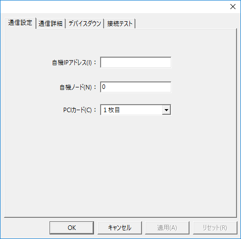
Communication Settings
|
•Your IP address
•Own machine node
•PCI Card
|
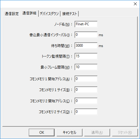
Communication details
|
•Node Name
•Write minimum communication interval
•Waiting time
•Token Monitoring Interval
•Minimum Frame Spacing
•Common memory 1 start address
•Common memory 1 start size
•Common memory 2 start address
•Common memory 2 start size |