About the connection example
Please see below for an example of connection settings for this driver.
Applicable models etc. |
explanation |
This is an example of connection settings with the FA-M3V series via FL-PCI.
|
*You can also connect to other devices using the same procedures as above.
Device List
The compatible devices are as follows (see here for how to view the device list).
device |
keyword |
Start address |
explanation |
unit |
reading |
Writing |
Common memory area 1 |
CA |
000 |
Decimal |
word |
○ |
● |
Common memory area 2 |
CB |
0000 |
Decimal |
word |
○ |
● |
|
VB, VW, VBI, VWI, YBI, YWI are unsupported devices. |
|
You can write to the common memory area of your own card, but you cannot write to the common memory area of the connected card. |
About connection protocols
The communication protocol used by the FL-PCI board is either FL-net (OPCN-2) Ver.1 or Ver.2. FutureNet Only Ver.2 can be used with FL-PCI boards from FL-PCI/V2-100 onwards. FL-net (OPCN-2) Ver.1 and Ver.2 are not compatible, and the two versions cannot be mixed on the same network.
For example, if you are using an FL-PCI board that only supports FL-net(OPCN-2) Ver.2, all devices that connect to FL-net must communicate in FL-net(OPCN-2) Ver.2, so please pay attention to the communication specifications of the connected devices.
board |
Available protocols |
FutureNet FL-PCI/V2 |
FL-net (OPCN-2 Ver.1) |
FL-net (OPCN-2 Ver.2) |
|
FutureNet FL-PCI/V2-100 |
FL-net (OPCN-2 Ver.2) |
FutureNet FL-PCI/V2-100L |
FL-net (OPCN-2 Ver.2) |
|
FutureNet FL-PCI/V2 supports different protocol versions depending on the firmware. Therefore, please check the firmware version in advance. |
Error Code List
The following error codes may occur when communicating with FL-net.
Error Codes |
explanation |
10 |
[Connect] CreateFile() failed. |
11 |
[Connect] DeviceIoControl() failed. |
12 |
[Connect] _pnpci == NULL. |
13 |
[Connect] Timeout. |
14 |
[Connect] Irregular ip. |
15 |
[Connect] No response from PCI card. |
16 |
[Connect] PCI card responded error. |
17 |
[AliveTest] Irregular response. |
18 |
[MessageSend] No respnse from PCI card. |
19 |
[MessageSend] Can't use buf. |
20 |
[MessageSend] Parameter Error. |
21 |
[MessageRecieve] GRAVE ERROR! |
22 |
[MessageRecieve] Timeout. |
23 |
[MessageRecieve] MESSAGEENDTABLE error. |
24 |
[ReadCyclicRelative] The node is not exist. |
25 |
[ReadCyclicRelative] The node is not data. |
26 |
[ReadCyclic] Can't use buf. |
27 |
[WriteCyclic] Can't write. |
28 |
[WriteCyclic] buffer full. |
29 |
[Common] System Error. |
32 |
[WriteCyclic] Can't finish to write. |
|
About error code "28" when writing If error code "28" occurs when writing continuously, adjust the minimum write communication interval from 5 ms to 5, 10, 15... in 5 ms increments.
|
How to calculate the token monitoring interval
To calculate the token monitoring interval, proceed as follows:
1.Number of frames = (Common memory 1 size + Common memory 2 size) × 2 / 1024
2.Token monitoring time > number of frames × (3ms + minimum frame interval / 10)
* The number of frames is rounded up to the nearest decimal point.
In the following example configuration:
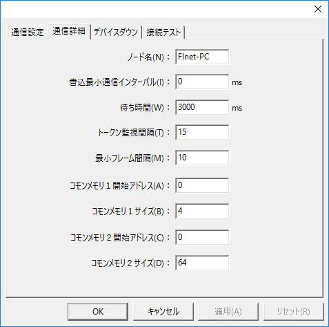
1.Number of frames = (4 + 64) × 2 / 1024 = 0.132 → 1 frame
2.1 frame × (3ms + 10 / 10) = 4ms
The token monitoring interval should be set to 5 ms or more, for example 15 ms to allow for some leeway.
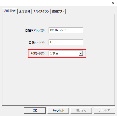
When installing two FL-PCI cards at the same time
Two FL-PCI cards can be installed in the same computer at the same time. When selecting the target card, select which card you want to access from "PCI Card" in the "Communication Settings" tab of the communication settings.
|
It is possible to install two cards, define two units, and communicate with each PCI card simultaneously. However, please note that the common memory of each PCI card cannot be referenced.
for example, 1st PCI card in unit 1 2nd PCI card in unit 2
If you specify this, unit 2 will not be able to reference the common memory of unit 1. Therefore, if you define the common memory of unit 1 for the tag of unit 2, a communication error will occur. |