overview
This is an example of connecting to a Yokogawa Electric FA-M3V series via FL-PCI. Connections to other devices can be made in a similar manner. In the following configuration, communication is performed via FL-net (OPCN-2 Ver.2) and a cyclic transmission connection is made.
Cyclic transmission provides a function that allows nodes performing transmission to treat the memory as a common one. The common memory is called "common memory" and there are two types, Area 1 and Area 2. The common memory is defined across the entire FL-net network as Area 1, which is 0.5K words, and Area 2, which is 8K words. A node can allocate its own data area to both Area 1 and Area 2. Areas are set in word units by specifying the top address and size of the area.
You can write (change the value) to the area you assigned to yourself. You cannot write to the areas of other nodes.
Model used
|
item |
Model etc. |
PLC side |
CPU |
SP71-4S |
Communication Unit |
LX02-1N |
|
PC side |
FL-net Board |
FutureNet FL-PCI/V2-100L |
Configuration environment
|
item |
Model etc. |
PLC side |
OS |
Windows8 Professional 64Bit |
tool |
WideField3 Ver R2.04 |
|
PC side |
OS |
Windows8.1Professional 64Bit |
Configuration details
item |
setting |
Setting items |
Configuration Example |
PLC side settings |
Switch Settings |
IP address |
192.168.250.2 |
Automatic configuration |
node |
2 |
|
Tool Settings |
Memory area 1 top |
4 |
|
Memory area 1 size |
4 |
||
Memory area 2 start |
4 |
||
Memory area 2 size |
4 |
||
Token Watch Time |
15 |
||
PC settings |
Unit Settings |
IP address |
192.168.250.1 |
node |
1 |
||
Tool Settings |
Memory area 1 top |
0 |
|
Memory area 1 size |
4 |
||
Memory area 2 start |
0 |
||
Memory area 2 size |
4 |
||
Token Watch Time |
15 |
||
Minimum Frame Spacing |
10 |
|
In the case of the FA-M3V series, the values of area 1 are linked to the link relay (L), and the values of area 2 are linked to the link register (W). Therefore, communication with the link relay and link register can be performed at high speed by connecting via cyclic transmission. |
PLC side settings
The FA-M3V series is configured using switches and WideField3, etc.
1.Set the switch as follows:
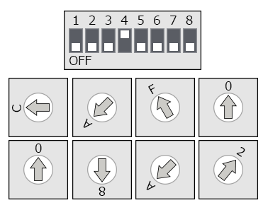
switch |
explanation |
Setting contents (hexadecimal) |
Condition SW1 |
OFF Fixed |
OFF |
Condition SW2 |
OFF Fixed |
OFF |
Condition SW3 |
OFF Fixed |
OFF |
Condition SW4 |
Communication port settings *The setting on the right is 10BASE-T |
ON |
Condition SW5 |
OFF Fixed |
OFF |
Condition SW6 |
OFF Fixed |
OFF |
Condition SW7 |
OFF Fixed |
OFF |
Condition SW8 |
OFF Fixed |
OFF |
IP Address SW1 |
IP address first digit setting ※Setting on the right is "192" |
C |
IP Address SW2 |
0 |
|
IP Address SW3 |
IP address first 2 digit setting *Setting on the right is "168" |
A |
IP Address SW4 |
8 |
|
IP Address SW5 |
IP address last 2 digit setting *Set the right side to "250" |
F |
IP Address SW6 |
A |
|
IP Address SW7 |
IP address last digit setting *Settings on the right are "2" |
0 |
IP Address SW8 |
2 |
|
Condition SW4 will be set to "Auto" when it is turned OFF. However, there are cases where auto negotiation does not work and connection is not possible due to 1:1 cross wiring or depending on the hub used. In that case, please specify 10BASE-T. |
|
The IP address is set using 16 rotary switches. Each digit of the IP address is expressed as a hexadecimal number. |
|
For details on the switch settings, etc., please refer to Yokogawa Electric's "FL-net (OPCN-2) Interface Module Instruction Manual." |
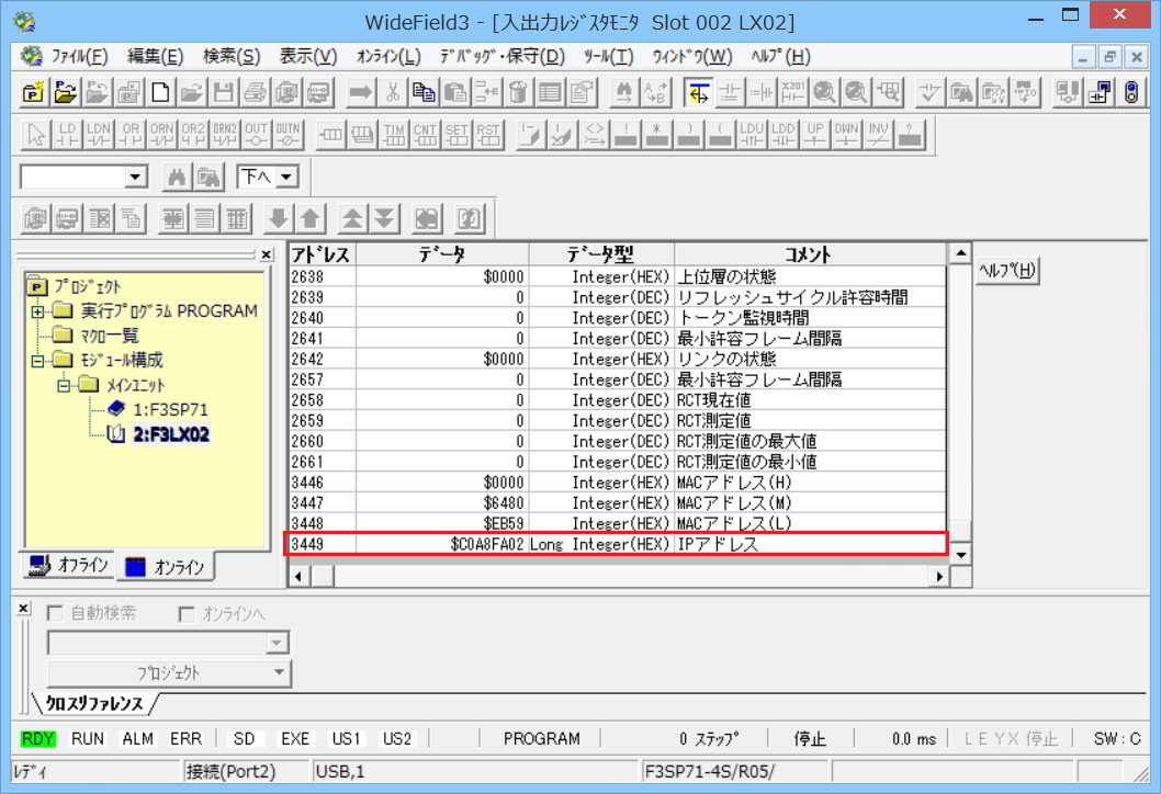
2.Connecting WideField3 to the CPU unit
3.Select the target communication unit (F3LX02) and check that the IP address is set correctly.
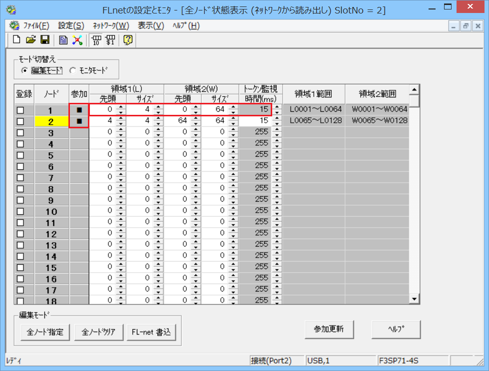
4.Select "Tools" - "I/O Module Settings" - "FL-net" to open the FL-net settings monitor.
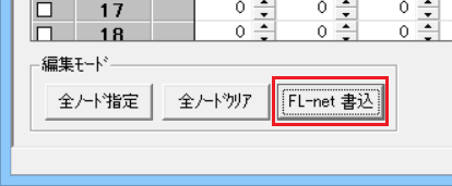
5.From "File" - "New", display the setting screen and set the following:
The setting is made for node "2." Since the fourth digit of the IP address is automatically used for the node, in this case it is "2" in "192.168.250.2."
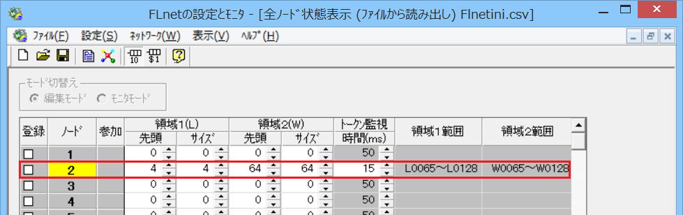
setting |
Setting contents |
Area 1 top |
4 |
Area 1 size |
4 |
Area 2 top |
64 |
Area 2 Size |
64 |
Token Watch Time |
15 * Set according to your environment |
6.Post from "FL-net" post
7.After writing is complete, configure the computer.
PC settings
The settings on the computer are as follows:
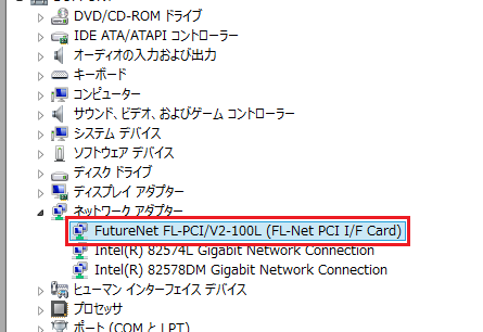
1.Check using Device Manager etc. to make sure the FL-net PCI board is installed correctly.
2.Start the server application, right-click "Application" - "Driver" in the tree, and select Add Driver.
3.Select the following units from the displayed driver list and add them:

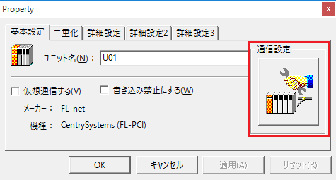
4.Open the properties of the added unit (U01) and click Communication Settings.
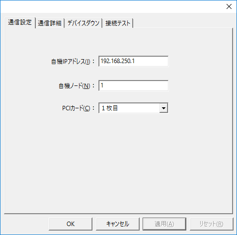
5.Set "Communication Settings" as follows:
item |
Setting contents |
IP address |
192.168.250.1 |
Node Number |
1 |
PC Cards |
1st photo |
6.Set "Communication Settings" as follows:
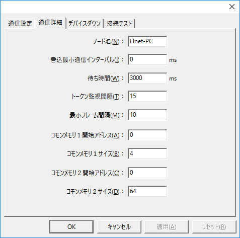
item |
Setting contents |
Node Name |
Freely set names |
Write minimum communication interval |
0 |
Waiting time |
3000 |
Token Monitoring Interval |
15 |
Minimum Frame Spacing |
10 |
Common memory start address 1 |
0 |
Common memory start 1 size |
4 |
Common memory start address 2 |
0 |
Common memory start 2 size |
64 |
|
The minimum write communication interval specifies the waiting time on the computer side from one write to the next. If the error code "28" occurs, adjust the minimum write communication interval from 5 ms to 5, 10, 15... in 5 ms increments.
|
|
Set an appropriate value for the token monitoring interval. For information on how to calculate the token monitoring interval, see "How to calculate the token monitoring interval." |
7.Check the connection
Please specify a device other than your own node as the destination node. Here, the FA-M3V node is specified.
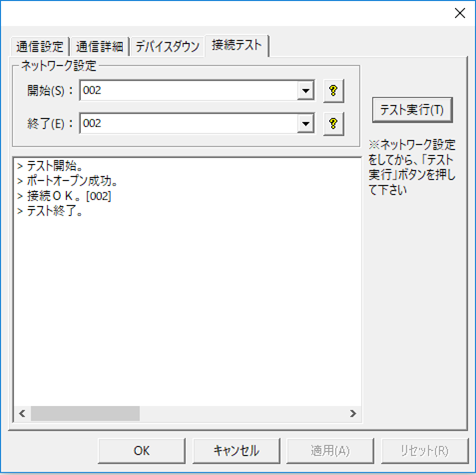
If a message such as "Connection OK" is displayed, the connection is confirmed.
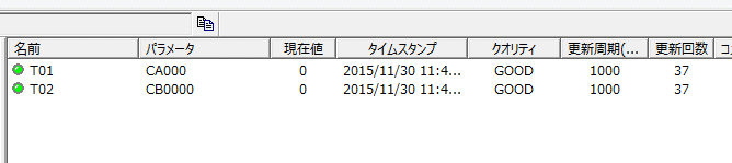
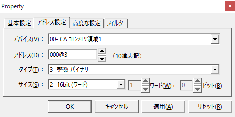
8.Configure tag settings
In this package, "CA" is used for communication with area 1. "CB" is used for communication with area 2. Addresses for area 1 can be set from 0 to 511. Addresses for area 2 can be set from 0 to 8191. Reading and writing can be done not only in word units, but also in bit units, byte units, double word units, and free units (any size from 1 to 32 bits).
|
Setting example) If you want to read and write bit-by-bit to the third bit of address "000" in area 1, set it as follows. |
9.Connect online and check that the tag is connected properly and that the tag quality is GOOD.
Confirmation of participation in FL-net
Once the settings on the PC are complete and the connection is OK, check the FL-net network status in WideField.
Click the "Update Participation" button in "FLnet Settings and Monitor" to check the network participation status. You can also display the common memory settings of other nodes (in this case, the FL-net board on the PC side) by selecting "Settings" - "FLnet All Node Status Display".