overview
This is a setting example for connecting to the H series via Ethernet.
Model used
item |
Model etc. |
PLC |
EH-150 (EH-CPU448A) |
Communication Unit |
ET-ETH |
Configuration environment
item |
environment |
OS |
Windows7 Professional 64Bit |
tool |
Internet Explorer 9 |
Configuration details
item |
setting |
Setting items |
Configuration Example |
PLC side settings |
Setting via switch and web browser |
IP address (temporary) |
192.168.0.10 |
IP address |
192.168.0.100 |
||
Subnet mask |
255.255.255.0 |
||
Timeout period |
30s |
||
Communication Protocol |
UDP |
||
Port number |
3004 |
||
PC settings |
Unit Settings |
IP address |
192.168.1.1 |
Port number |
Automatic |
||
Communication Protocol |
UDP |
||
Maximum Communication Interval |
30 (fixed) |
||
Folder and communication test settings |
Loop No. |
FF (default value) |
|
Unit No. |
FF (default value) |
* Most of the settings on the computer will be adjusted to match the settings on the unit.
PLC side settings
Configure the PLC side.
1.Set the front switch of "ET-ETH"
If you are using
EH-ETH for the first time or do not know the configured IP address, this setting is not necessary if you know the already configured IP address from the dip switch on the front of the unit.
Here, set the IP address to "192.168.0.10" as a temporary setting.
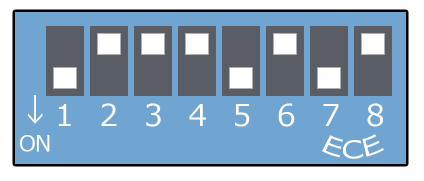
switch |
explanation |
Setting contents (hexadecimal) |
Switch 1 |
WEB Browser Settings Mode |
ON |
Switch 2 |
OFF |
|
Switch 3 |
Specify the end of the IP address in binary. (Can be specified in the range of 1 to 63) |
OFF |
Switch 4 |
OFF |
|
Switch 5 |
ON |
|
Switch 6 |
OFF |
|
Switch 7 |
ON |
|
Switch 8 |
OFF |
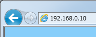
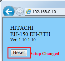
2.WEBLaunch a browser (such as IE) and access the IP address set on the switch.
If you are not using the
switch, access the server using the configured IP address.
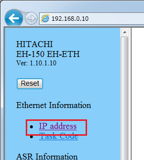
3.When the setting screen appears, select "IP address" from the left menu.
4.From the IP address setting screen, select "Setting"
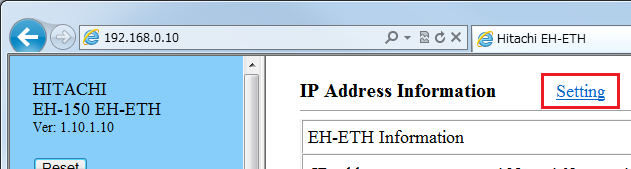
5.Set the IP address and subnet mask as follows:
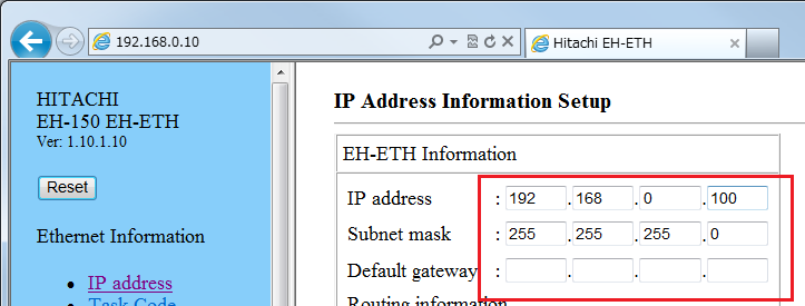
setting |
Setting contents |
IP address |
192.168.0.100 |
Subnet mask |
255.255.255.0 |
6.Once you have completed the settings, click the "Set" button at the bottom of the page to confirm the settings.
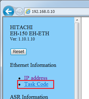
7.Select "Task Code" from the left menu.
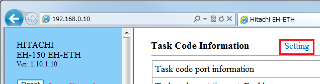
8.From the task code setting screen, select "Setting"
9.Configure as follows:
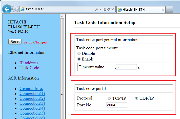
setting |
Setting contents |
Task code port timeout: |
Enable |
Timeout value |
30s |
Task code port 1 Protocol |
UDP |
Task code port 1 Port No. |
3004 |
10.Once you have completed the settings, click the "Set" button at the bottom of the page to confirm the settings.
11.Press Reset on the left menu
After the reset is complete, turn off the power to the PLC, return all DIP switches to OFF, and then turn the power back on.
PC settings
Use the Server application to connect to the PLC for which you have set up communications.
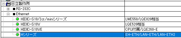
1.Right-click "Application" - "Driver" in the tree and select Add Driver.
2.Select the following units from the displayed driver list and add them:
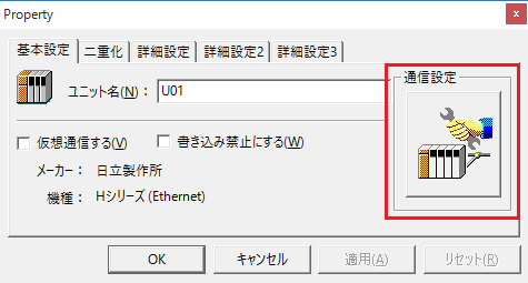
3.Open the properties of the added unit (U01) and click Communication Settings.
4.Configure the following in "PC Settings"
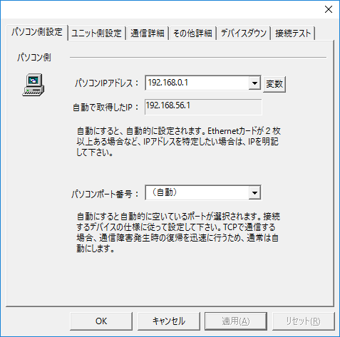
setting |
Setting contents |
Computer IP address |
192.168.0.1 |
Computer port number |
Automatic |
5.Set the following in "Unit side settings"
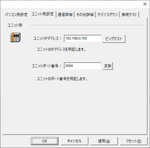
setting |
Setting contents |
Unit IP Address |
192.168.0.100 |
Unit Port Number |
3004 |
6.Set "Communication details" as follows:
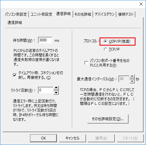
setting |
Setting contents |
protocol |
UDP/IP |
Maximum communication interval |
30 (fixed) |
7.Select "Ping Test" to check if the ping goes through normally.
If you see a message like "Ping test is success~", the test was successful.
8.Perform a connection test to check the connection
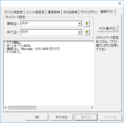
If a message such as "Connection OK" is displayed, the connection is confirmed to be OK.