overview
This is a setting example for connecting the HIDIC-S10VE series to the built-in Ethernet port of the CPU.
Model used
item |
Model etc. |
PLC |
HIDIC-S10VE LQP600 |
Communication Unit |
CPU Attached Port |
Configuration environment
item |
environment |
OS |
Windows10 Professional 64Bit |
tool |
BASE SYSTEM / S10VE |
Configuration details
item |
setting |
Setting items |
Configuration Example |
PLC side settings |
Set with tools |
Station Number |
FE |
IP address |
192.168.0.1 |
||
Port number |
4312 |
||
PC settings |
Unit Settings |
IP address |
192.168.0.10 |
Port number |
Automatic |
||
Communication Protocol |
TCP/IP (fixed) |
* Most of the settings on the computer will be adjusted to match the settings on the unit.
|
The port numbers on the PLC side that can be used for connection are "4312 to 4315." Port 4312 is used for connections between PLC and BASE SYSTEM. Therefore, if you are connecting to both BASE and SYSTEM at the same time, change the port number on the PLC side to 4313, for example. |
PLC side settings
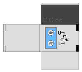
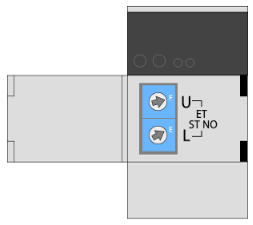
Set it to "LQP600". The setting is done using the rotary switch attached to the CPU and BASE SYSTEM.
1.Set the front switch of the CPU unit as follows:
|
Set the station number with the front switch. During initial setup, it is necessary to connect with the default IP address, so specify "0xFF". |
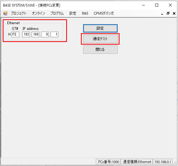
2.Start BASE SYSTEM and connect to PLC
Select "Online" - "Change connected PCs", configure the following settings, and click "Settings".
After completing the settings, click "Communication Test" to check that communication is possible.
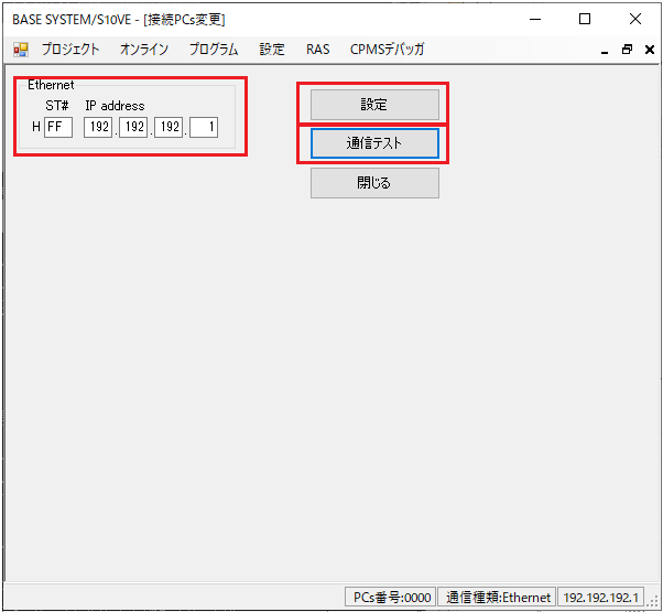
setting |
Setting contents |
ST# |
FF |
IP address |
192.192.192.1 |
|
If the station number is "0xFF" and you are using Ethernet port 1, the IP address will be "192.192.192.1". If you are using Ethernet port 2, the IP address will be "192.192.193.1". Please note that the IP address will differ depending on the Ethernet port you use. |
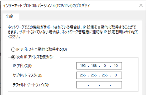
|
The IP address of the PC must be set to an IP address in the same segment as the PLC. Example: 192.192.192.10 etc. |
3.Select "Project" - "Network Settings" - "Ethernet" and set the following:
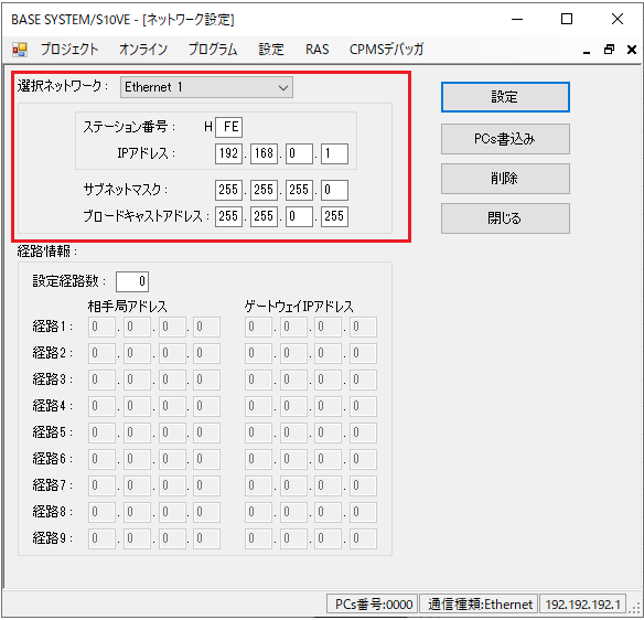
setting |
Setting contents |
Selection Network |
Ethernet1 |
Station Number |
FE |
IP address |
192.168.0.1 |
Subnet mask |
255.255.255.0 (set according to your environment) |
Broadcast Address |
255.255.0.255 (set according to your environment) |
|
If you are using ET.NET (LQE260-E, etc.), please configure it from "Project" - "Network Settings" - "ET.NET". |
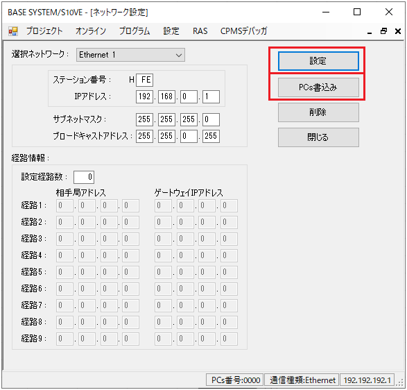
4.After setting, click "Set" to confirm the setting, then click "Write PCs"
After writing, click "Close" to close the settings screen.
5.Turn the power of the main unit OFF, change the station number as follows, and then turn the power ON again.
|
Set the switch to match the station number specified in BASE or SYSTEM. |
|
When changing the switch, be sure to turn off the PLC power before doing so. |
|
If you are using ET.NET (LQE260-E) and wish to communicate with a specified IP address, the station number of ET.NET must be "0x00." Please note that you cannot use anything other than "0x00." |
6.Change the IP address of the computer to 192.168.0.10
7.Select "Online" - "Change connected PCs" and perform a connection test with the station number and IP address you set.
If the connection test is successful, the unit's IP address has been set correctly.
PC settings
Use the Server application to connect to the PLC for which you have set up communications.
1.Right-click "Application" - "Driver" in the tree and select Add Driver.
2.Select the following units from the displayed driver list and add them:
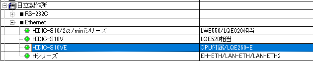
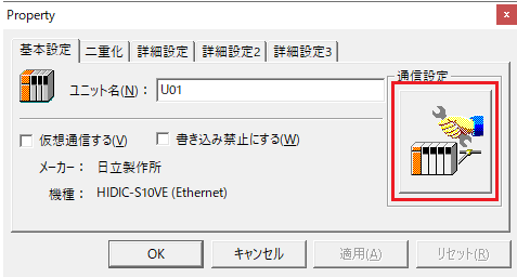
3.Open the properties of the added unit (U01) and click Communication Settings.
4.Configure the following in "PC Settings"
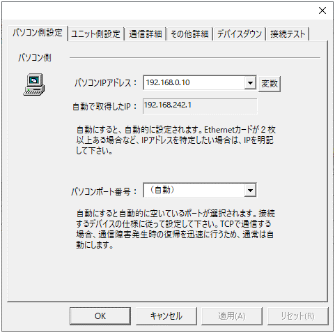
setting |
Setting contents |
Computer IP address |
192.168.0.10 |
Computer port number |
Automatic |
5.Set the following in "Unit side settings"
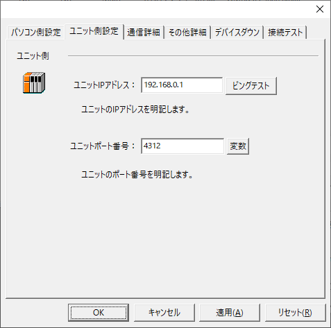
setting |
Setting contents |
Unit IP Address |
192.168.0.1 |
Unit Port Number |
4312 |
6.Select "Ping Test" to check if the ping goes through normally.
If you see a message such as "Ping test is success~", the test was successful.
7.Perform a connection test to check the connection
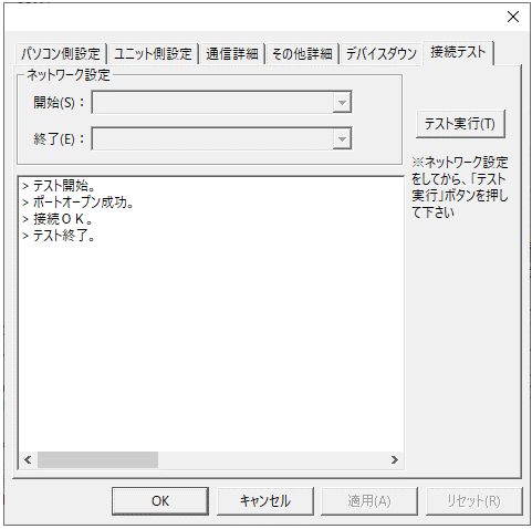
If a message such as "Connection OK" is displayed, the connection is confirmed to be OK.