overview
This is an example of setting up an Ethernet connection to KV-5000.
Model used
item |
Model etc. |
PLC |
KV-5000 |
Communication Unit |
CPU Attached Port |
Configuration environment
item |
environment |
OS |
Windows7 Professional 64Bit |
tool |
KV STUDIO 6.13 |
Configuration details
item |
setting |
Setting items |
Configuration Example |
PLC side settings |
Set with tools |
IP address |
192.168.0.100 |
Subnet mask |
255.255.255.0 |
||
Port number (upper link) |
8501 |
||
PC settings |
Unit Settings |
IP address |
192.168.0.1 |
Port number |
Automatic |
* Most of the settings on the computer will be adjusted to match the settings on the unit.
PLC side settings
Configure the KV-5000. The configuration is done using KV STUDIO etc.
1.Start KV STUDIO and create a new project
2.Open the menu "Monitor/Simulator" - "Communication Settings" - "Communication Settings" and confirm that communication with PLC is possible.
3.Select the added unit in the workspace's unit configuration and double-click it.
4.From the unit editor, select "File" - "Load unit configuration from PLC" to load configuration information from PLC.
5.Configure the settings as follows, click the "Apply" button, and close the dialog.
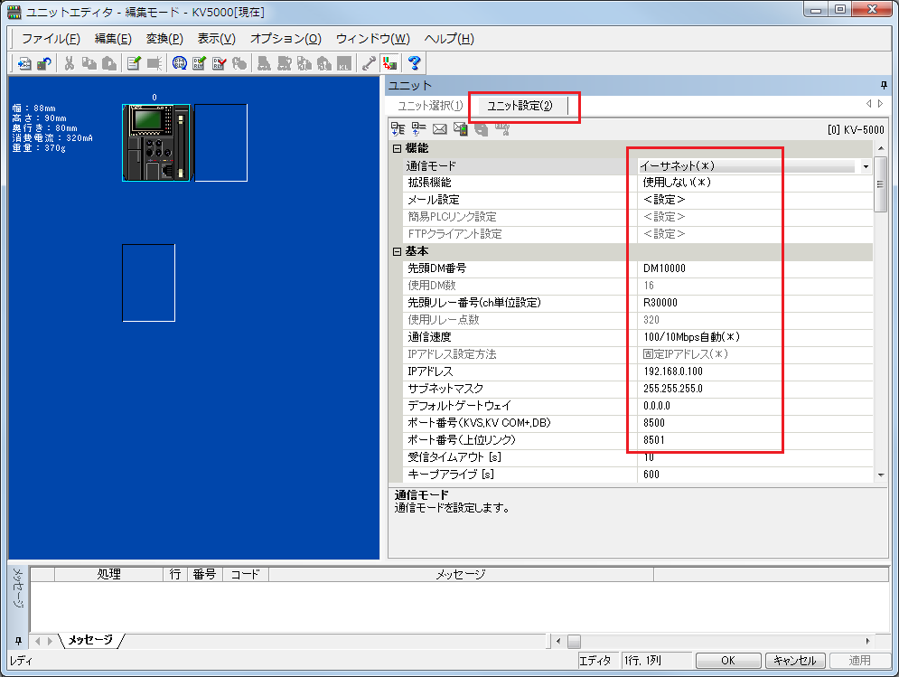
setting |
Setting contents |
Communication Mode |
Ethernet |
First DM |
DM10000 (Set the first number of the DM used in the unit) |
First relay number (channel unit setting) |
R30000 (Set the first relay number used in the unit) |
IP address |
192.168.0.100 |
Subnet mask |
255.255.255.0 |
Port number (upper link) |
8501 |
|
For detailed settings such as the first DM, please refer to the Keyence "Ethernet Unit KV-LE20" User's Manual. |
6.From the menu, select "Monitor/Simulator" - "PLC Transfer" to display the program transfer dialog, check the necessary items, and then write the parameters to the PLC.
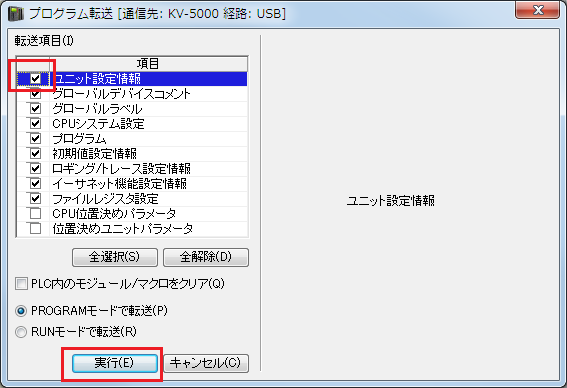
|
After setting the parameters, you must turn off the power to the PLC once to reflect the settings. Although a remote reset may be possible from the tool, we recommend turning off the power once to ensure that the settings are reflected. |
|
Some settings cannot be transferred in RUN mode, so in that case please transfer them in PROGRAM mode. |
PC settings
Use the Server application to connect to the PLC for which you have set up communications.
1.Right-click "Application" - "Driver" in the tree and select Add Driver.
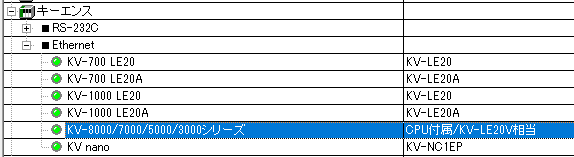
2.Select the following units from the displayed driver list and add them:
When connecting to the
KV nano series, select the "KV nano" driver.
3.Open the properties of the added unit (U01) and click Communication Settings.
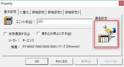
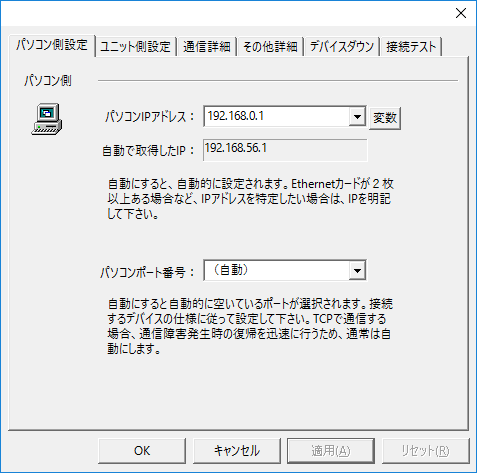
4.Configure the following in "PC Settings"
setting |
Setting contents |
Computer IP address |
192.168.0.1 |
Computer port number |
Automatic |
|
Since it is not possible to specify the port number of the connection destination on the PLC side, please set the port number on your computer to "Automatic." |
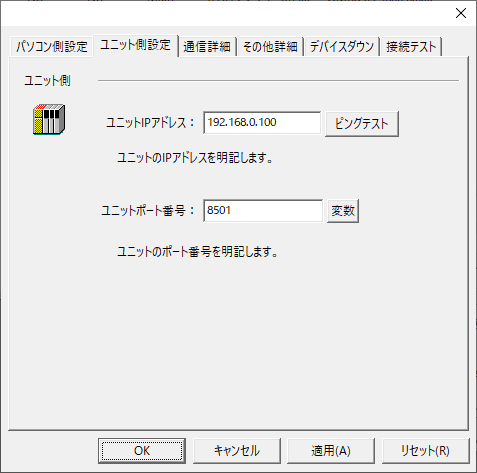
5.Set the following in "Unit side settings"
setting |
Setting contents |
Unit IP Address |
192.168.0.100 |
Unit Port Number |
8501 |
6.Select "Ping Test" to check if the ping goes through normally.
If you see a message like "Ping test is success~", the test was successful.
7.Perform a connection test to check the connection
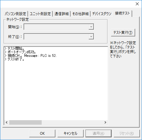
If a message such as "Connection OK" is displayed, the connection is confirmed to be OK.