overview
This is an example of how to set up an RS-232C connection with KV-1000.
Model used
item |
Model etc. |
PLC |
KV-1000 |
Communication Unit |
KV-L20R |
Configuration environment
item |
environment |
OS |
Windows7 Professional 64Bit |
OS |
KV STUDIO 6.13 |
Configuration details
item |
setting |
Setting items |
Configuration Example |
PLC side settings |
Set with tools |
Operational Mode |
Link Mode |
baud rate |
19200bps |
||
Data bit length |
8bits |
||
Stop bits |
1bits |
||
parity |
Even |
||
PC settings |
Unit Settings |
COMM |
Communication port number to connect to |
Transmission speed |
19200bps |
||
Byte Size |
8bits |
||
Stop bits |
1bits |
||
parity |
Even |
||
Folder and communication test settings |
Unit No. |
0 |
* Most of the settings on the computer will be adjusted to match the settings on the unit.
PLC side settings
Configure the KV-1000. The configuration is done using KV STUDIO etc.
1.Start KV STUDIO and create a new project
2.Open the menu "Monitor/Simulator" - "Communication Settings" - "Communication Settings" and confirm that communication with PLC is possible.
3.Select the added unit in the workspace's unit configuration and double-click it.
4.From the unit editor, select "File" - "Load unit configuration from PLC" to load configuration information from PLC.
5.Configure the settings as follows, click the "Apply" button, and close the dialog.
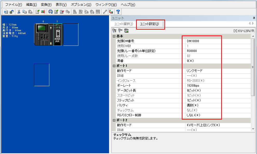
setting |
Setting contents |
First DM |
DM10000 (Set the first number of the DM used in the unit) |
First relay number (channel unit setting) |
R30000 (Set the first relay number used in the unit) |
Communication Mode |
Link Mode |
baud rate |
19200bps |
Data bit length |
8-bit |
Stop bits |
1 bit |
parity |
Even |
|
For detailed settings such as the first DM, please refer to the Keyence "Multi Communication Unit KV-L20" user manual.
|
6.From the menu, select "Monitor/Simulator" - "PLC Transfer" to display the program transfer dialog, check the necessary items, and then write the parameters to the PLC.
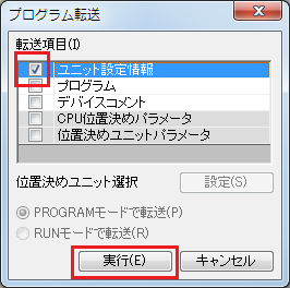
|
After setting the parameters, you must turn off the power to the PLC once to reflect the settings. Although a remote reset may be possible from the tool, we recommend turning off the power once to ensure that the settings are reflected. |
|
Some settings cannot be transferred in RUN mode, so in that case please transfer them in PROGRAM mode. |
PC settings
Use the Server application to connect to the PLC for which you have set up communications.
1.Right-click "Application" - "Driver" in the tree and select Add Driver.
2.Select the following units from the displayed driver list and add them:
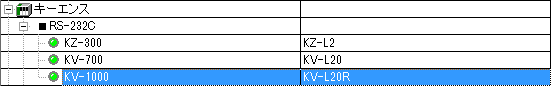
3.Open the properties of the added unit (U01) and click Communication Settings.
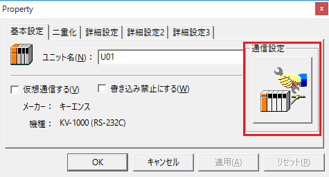
4.Set "Communication Settings" as follows:
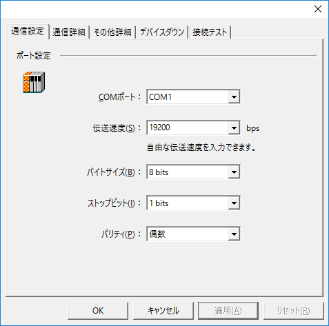
setting |
Setting contents |
COMPort |
Communication port number to connect to |
Transmission speed |
19200 |
Byte Size |
8bits |
Stop bits |
1bits |
parity |
Even |
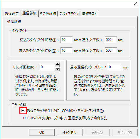
5.USB-RS-If you are using a 232C conversion cable, the COM port may be locked in the event of a communication error, so check the reopen setting.
6.Perform a connection test to check the connection
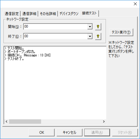
If a message such as "Connection OK" is displayed, the connection is confirmed to be OK.