overview
This is a setting example for connecting to the QnA series via Ethernet.
Model used
item |
Model etc. |
PLC |
Q2ACPU |
Communication Unit |
AJ71QE71 |
Configuration environment
item |
environment |
OS |
Windows7 Professional 64Bit |
tool |
GX-Developer Ver8.114U |
Configuration details
item |
setting |
Setting items |
Configuration Example |
PLC side settings |
Setting with switches and tools |
IP address |
192.168.0.100 |
Port number |
8192 (2000 hex) |
||
Communication data code setting |
Binary Code Communication |
||
PC settings |
Unit Settings |
IP address |
192.168.0.1 |
Port number |
8193 (2001 hex) |
||
Communication Protocol |
UDP |
||
Folder and communication test settings |
Network Number |
0 |
|
PC Number |
FF |
||
Request unit I/O number |
03FF |
* Most of the settings on the computer will be adjusted to match the settings on the unit.
|
You need to set the IP address and port number for the ladder from GX-Developer. In this case, set it in hexadecimal. You can also set the port number freely. The port number on the PC side and the PLC side can be the same. |
PLC side settings
Set up "AJ71QE71". Settings are made using the front switches and GX-Developer.
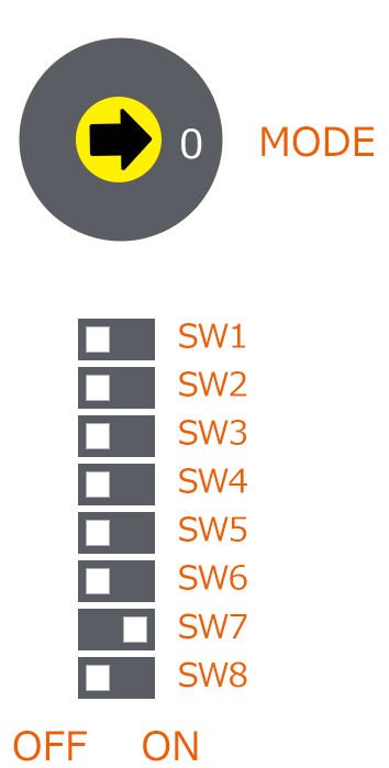
1.Set the switch as follows:
|
*Since communication is carried out in binary code, set "SW2" to OFF. |
2.Start GX-Developer and confirm that you can connect to PLC
3.Write the following ladder in GX-Developer
For "AJ71QE71", you need to initialize the IP address etc. with the ladder. Add the ladder below to the PLC.
This program is based on the program at the end of the "QnA Compatible Ethernet Interface Unit" manual published by Mitsubishi Electric.
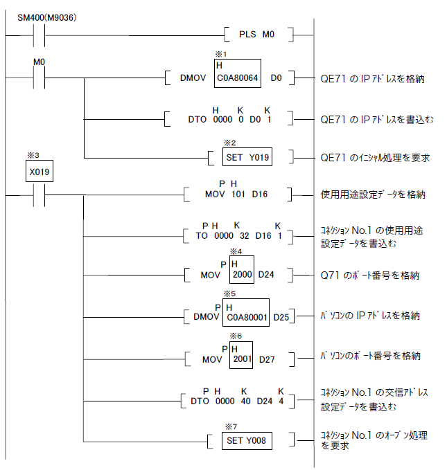
※1 This is the IP address of PLC. Please set it in hexadecimal. Example) 192.168.0.100 → C0A80064
※4 PLC port number. Please set it in hexadecimal. Example) 8192 (decimal) → 2000 (hexadecimal)
※5 This is the IP address of the computer. Please set it in hexadecimal. Example) 192.168.0.1 → C0A80001
※6 This is the computer's port number. Please set it in hexadecimal. Example: 8193 (decimal) → 2001 (hexadecimal)
*2, *3, *7 In the above examples, when QE71 is assigned to slot 0, X/Y000 to X/Y01F will be automatically assigned.
Change the address depending on the slot position.
|
There are some points to note about the connection test. Since the connection test uses a loopback test command, it cannot be tested against other QC24 stations via the data link system or network system. |
4.Write the ladder to the PLC by selecting "Online" - "Write to PC", then reset and reflect the ladder.
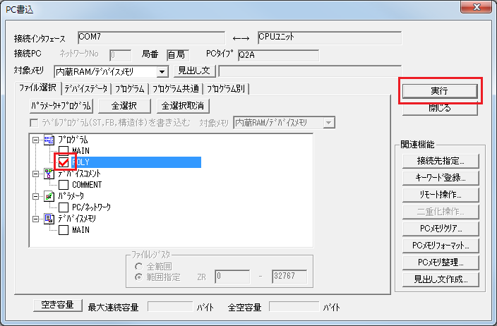
Here, we write "POLY" because we set the ladder in the program "POLY". To reset, insert a key into the CPU and turn it to "RESET".
PC settings
Use the Server application to connect to the PLC for which you have set up communications.
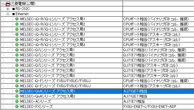
1.Right-click "Application" - "Driver" in the tree and select Add Driver.
2.Select the following units from the displayed driver list and add them:
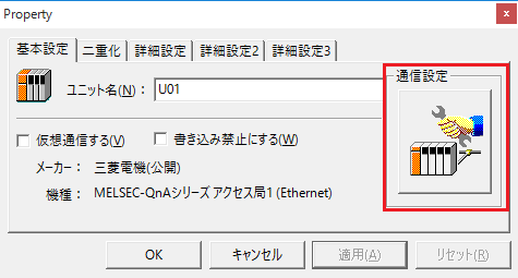
3.Open the properties of the added unit (U01) and click Communication Settings.
4.Configure the following in "PC Settings"
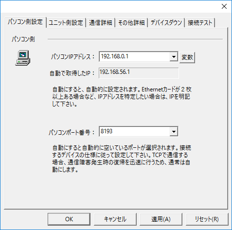
setting |
Setting contents |
Computer IP address |
192.168.0.1 |
Computer port number |
8193 (specified in decimal) |
5.Set the following in "Unit side settings"
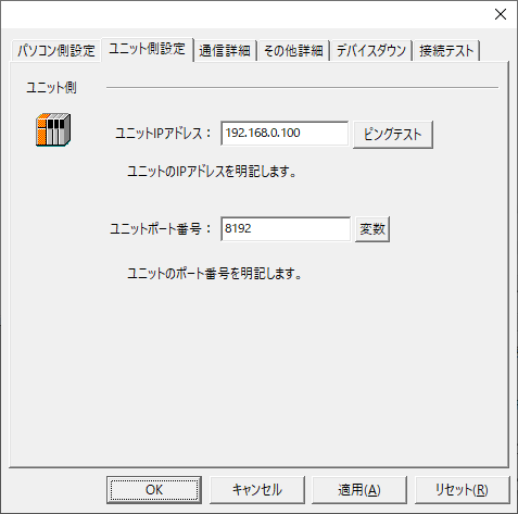
setting |
Setting contents |
Unit IP Address |
192.168.0.100 |
Unit Port Number |
8192 (specified in decimal) |
6.Select "Ping Test" to check if the ping goes through normally.
If you see a message like "Ping test is success~", the test was successful.
7.Select the protocol in "Communication Details"
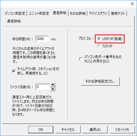
setting |
Setting contents |
protocol |
UDP (recommended) |
8.Perform a connection test to check the connection
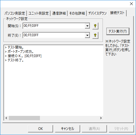
If a message such as "Connection OK" is displayed, the connection is confirmed to be OK.
|
The CPU monitoring timer can be set in the "Other detailed settings" in the unit's communication settings dialog. The CPU monitoring timer is the waiting time on the PLC side from receiving a command from the computer until returning a response to that command. If you are referencing other PLC devices via MELSECNET or CC-Link, be sure to set an appropriate time (if you set the CPU monitoring timer to 0 and the other PLC goes into a state where its power is cut off, Ethernet communication itself will be disabled). For details, refer to the PLC manual. |