overview
This is a setting example for connecting to the CP1E series via Ethernet. In this example, communication is performed using the auto-generation method.
Model used
item |
Model etc. |
PLC |
CP1E (NA) |
Communication Unit |
CP1W-CIF41 |
Configuration environment
item |
environment |
OS |
Windows7 Professional 64Bit |
tool |
InternetExplorer 11 |
Configuration details
item |
setting |
Setting items |
Configuration Example |
PLC side settings |
WEBSettings in browser |
IP address |
192.168.0.100 |
Subnet mask |
255.255.255.0 |
||
Port number |
9600 |
||
FINS Node |
100 (the end of the IP address) |
||
IP address conversion method |
Automatic generation method |
||
PC settings |
Unit Settings |
IP address |
192.168.0.1 |
Port number |
9600 |
||
Folder and communication test settings |
Source Network Number |
000 |
|
Source Node |
999 |
||
Destination network number |
000 |
||
Destination Node |
999 |
* Most of the settings on the computer will be adjusted to match the settings on the unit.
|
In this connection example, the IP address conversion method is set to "automatic generation method." |
PLC side settings
Configure "CP1W-CIF41". The settings are configured using a web browser.
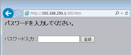
1.Connect to the following URL using InternetExplorer.

|
The URL differs for each of the following display languages, so please select the language that best suits your situation.
|
2.Enter your password and click "Register"
If you have not registered a password, specify the default password. For the default password, refer to the OMRON manual "CP Series CP1L CPU Unit."
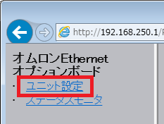
3.Click "Unit Settings"
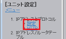
4.Click "IP Addresses and Protocols" - "Settings"
5.Set the IP address and other settings as follows. After setting, click "Transfer" to write the settings.
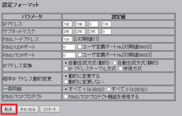
setting |
Setting contents |
IP address |
192.168.0.100 |
Subnet mask |
255.255.255.0 (Please set according to your environment) |
FINS Node Address |
100 (This must match the last value of the IP address you set.) |
IP Address Translation |
Automatic generation method (dynamic) |
*Please set other settings according to your environment. Here, the default values are used for other settings.
6.To reflect the settings, turn off the power to the PLC and then restart it.
7.Issue a PING command from the command prompt to check that the IP address has been set correctly.
PC settings
Use the Server application to connect to the PLC for which you have set up communications.
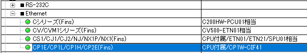
1.Right-click "Application" - "Driver" in the tree and select Add Driver.
2.Select the following units from the displayed driver list and add them:
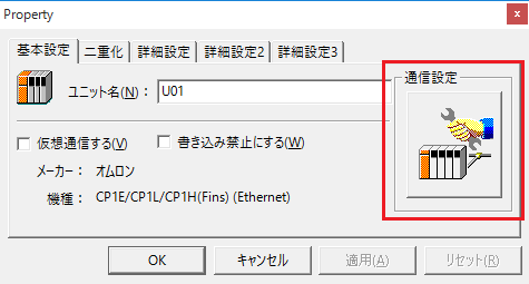
3.Open the properties of the added unit (U01) and click Communication Settings.
4.Configure the following in "PC Settings"
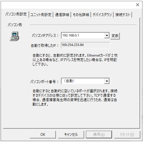
setting |
Setting contents |
Computer IP address |
192.168.0.1 |
Computer port number |
9600 |
5.Set the following in "Unit side settings"
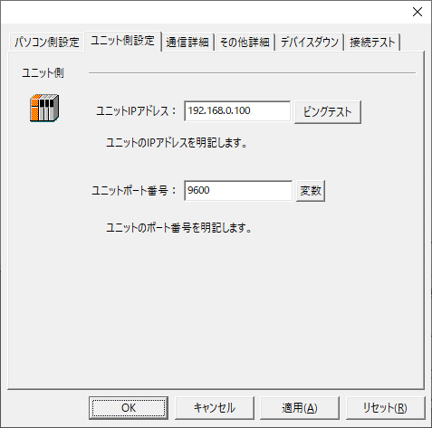
setting |
Setting contents |
Unit IP Address |
192.168.0.100 |
Unit Port Number |
9600 |
6.Select "Ping Test" to check if the ping goes through normally.
If you see a message like "Ping test is success~", the test was successful.
7.Select the protocol in "Communication Details"
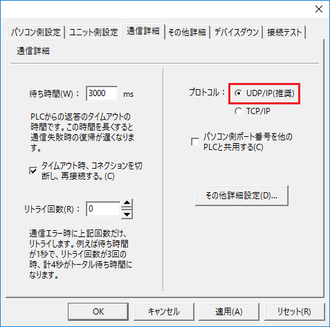
setting |
Setting contents |
protocol |
UDP (recommended) |
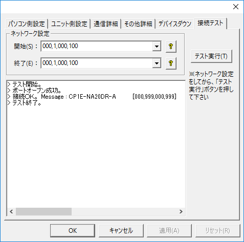
8.Perform a connection test to check the connection
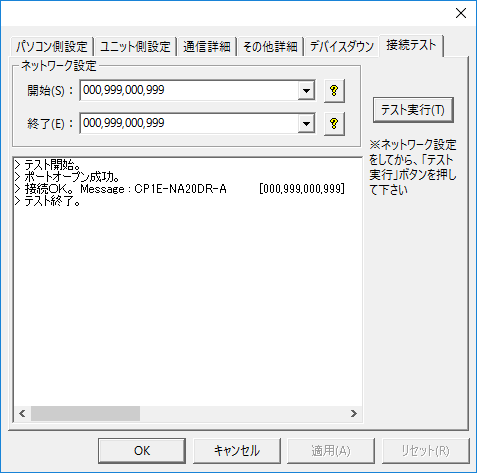
If a message such as "Connection OK" is displayed, the connection is confirmed to be OK.
|
When testing the connection and setting up the folder, do not forget to specify the node (network settings).
•Source/Destination Network Number: Please specify the network number. Specifying 000 will indicate your own network. •The source/destination node sets the node. If you specify 999, the last part of the IP address will be the node.
If you connect using the settings in this example, you can also connect by specifying "000,1,000,100".
|