overview
This is a setting example for connecting to a Siemens S7-300 via Ethernet.
The S7-300/400 can be configured using STEP7 (TIA Potal V13).
On the other hand, if you are using an older model, STEP7 (TIA Potal V13) is not compatible and you will need to use SIMATIC Manager. Please refer to this setting example when using SIMATIC Manager.
Model used
item |
Model etc. |
PLC |
S7-300 |
Communication Unit |
CPU 315-2 PN/DP |
Configuration environment
item |
environment |
OS |
WindowsXP Professional 32Bit |
tool |
SIMATIC Manager Ver505.100 |
Configuration details
item |
setting |
Setting items |
Configuration Example |
PLC side settings |
Set with tools |
IP address |
192.168.1.100 |
Port number |
102 (default port) |
||
Subnet mask |
255.255.255.0 |
||
PC settings |
Unit Settings |
IP address |
192.168.1.1 |
Port number |
Automatic |
||
Communication Protocol |
TCP/IP |
* Most of the settings on the computer will be adjusted to match the settings on the unit.
PLC side settings
Configure the "S7-300". The configuration is done in SIMATIC Manager.
1.Start "SIMATIC Manager" and select "File" - "New" from the menu to display the "New Project" screen below.
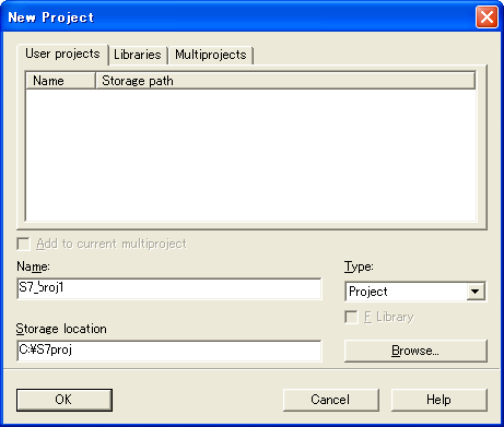
2.Set the project name and location, then click the "OK" button to create a new project.
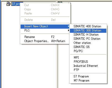
3.Right-click the project name displayed in the tree view, select "SIMATIC 300 Station" and create a new object.
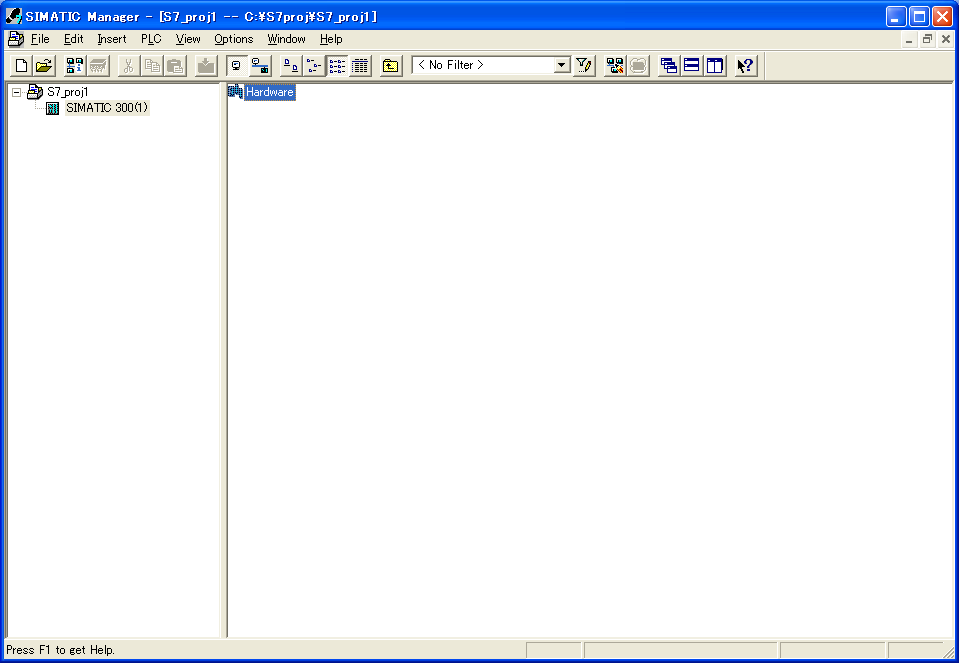
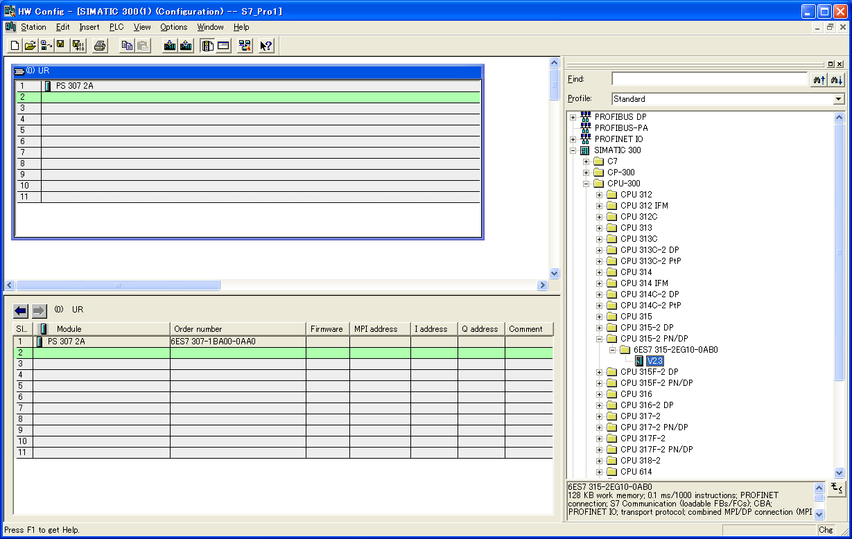
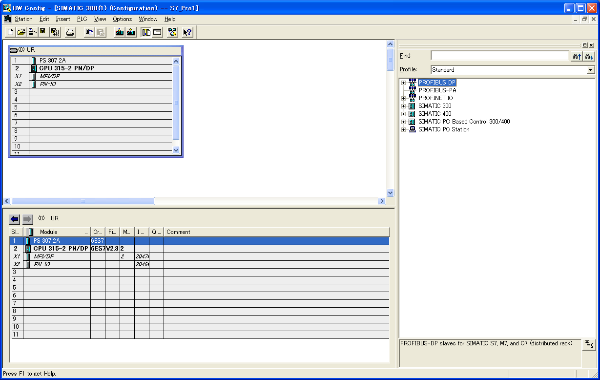
4.Select "SIMATIC 300" in the tree view and double-click "Hardware" in the left view to display the "HW Config" screen.
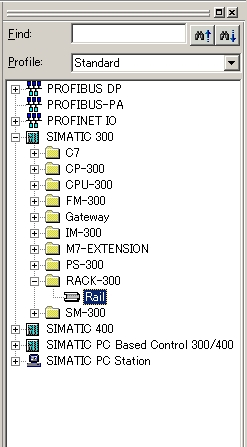
5.Add "Rail" from "Hardware Catalog" on the "HW Config" screen that appears.
6.Add a power supply unit (in this example, "PS 307 2A") from "Hardware Catalog"
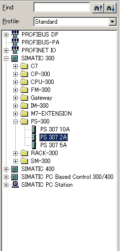
7.Next, add the CPU (in this example, "CPU 315-2 PN/DP") from "Hardware Catalog".
8.When hardware with Ethernet I/F is added, the following "Ethernet interface" setting screen will be displayed.
9.Set the IP address, subnet mask, etc. of PLC
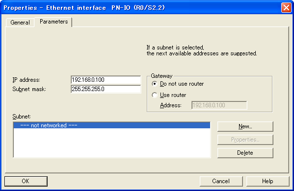
setting |
Setting contents |
IP address |
192.168.0.100 |
Subnet mask |
255.255.255.0 |
10.To create a "Subnet", click the "New" button on this screen.
11.On the displayed "New subnet Industrial Ethernet" setting screen, set the subnet name, etc.
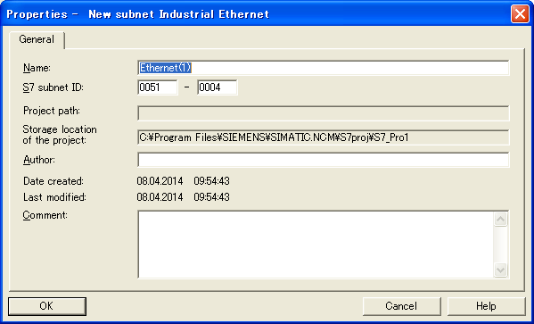
12.Click the "OK" button to return to the "Ethernet interface" setting screen, then click the "OK" button
13.After all the settings are complete, download the settings to PLC and apply them.
PC settings
Use the Server application to connect to the PLC for which you have set up communications.
1.Right-click "Application" - "Driver" in the tree and select Add Driver.
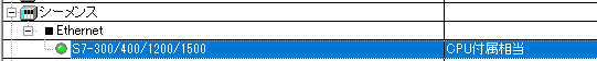
2.Select the following units from the displayed driver list and add them:
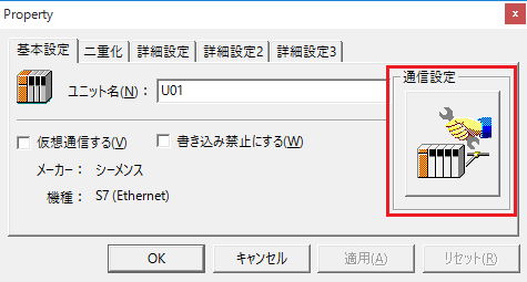
3.Open the properties of the added unit (U01) and click Communication Settings.
4.Configure the following in "PC Settings"
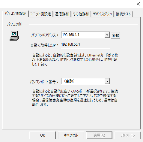
setting |
Setting contents |
Computer IP address |
192.168.1.1 |
Computer port number |
Automatic |
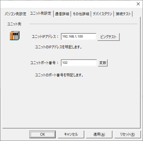
5.Set the following in "Unit side settings"
setting |
Setting contents |
Unit IP Address |
192.168.1.100 |
Unit Port Number |
102 (The destination port cannot be specified, so the default port of 102 is used.) |
6.Select "Ping Test" to check if the ping goes through normally.
If you see a message like "Ping test is success~", the test was successful.
7.Perform a connection test to check the connection
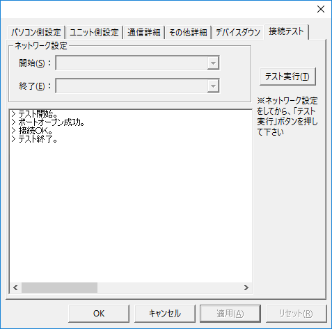
If a message such as "Connection OK" is displayed, the connection is confirmed to be OK.