overview
This is an example of setting up an Ethernet connection to CPU301.
Model used
item |
Model etc. |
PLC |
CPU301 |
Communication Unit |
CPU Attached Port |
Configuration environment
item |
environment |
OS |
Windows7 Professional 64Bit |
tool |
MPE720 Ver7.28.0100 |
Configuration details
item |
setting |
Setting items |
Configuration Example |
PLC side settings |
Set with tools |
IP address |
192.168.0.100 |
Subnet mask |
255.255.255.0 |
||
Gateway IP Address |
0.0.0.0 |
||
Port number |
10001 |
||
PC settings |
Unit Settings |
IP address |
Automatic |
Port number |
Automatic |
||
Communication Protocol |
UDP |
||
Folder and communication test settings |
CPU Number |
01 |
* Most of the settings on the computer will be adjusted to match the settings on the unit.
PLC side settings
Set up "CPU301". The settings are done on MPE720.
1.Select "Online" - "Connect" from the menu and connect to PLC.
2.Select "Module Configuration Definition"
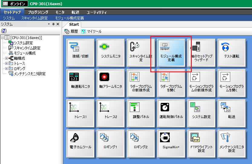
3.When the module configuration definition window appears, double-click "218IFD."
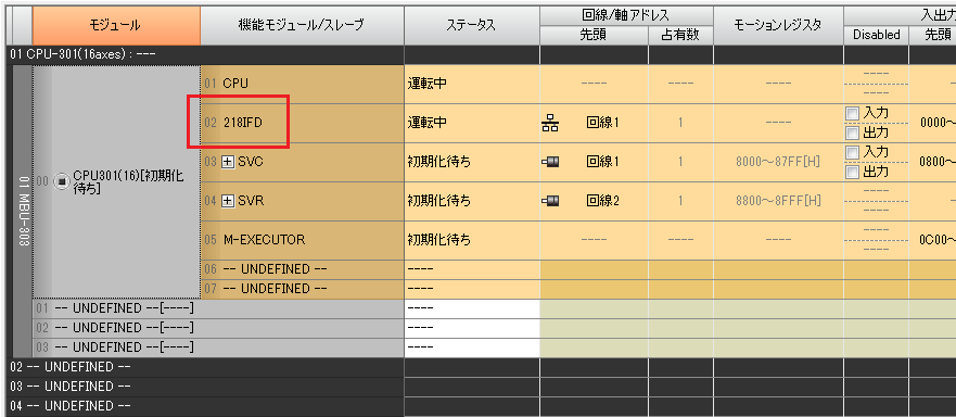
4.When the detailed definition window opens, set the parameters as follows:
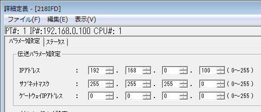
setting |
Setting contents |
IP address |
192.168.0.100 |
Subnet mask |
255.255.255.0 |
Gateway IP Address |
0.0.0.0 |
5.Click the "Easy Settings" button to display the settings screen.
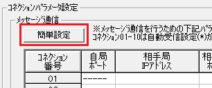
6.Set the connection parameters as follows and click the "OK" button.
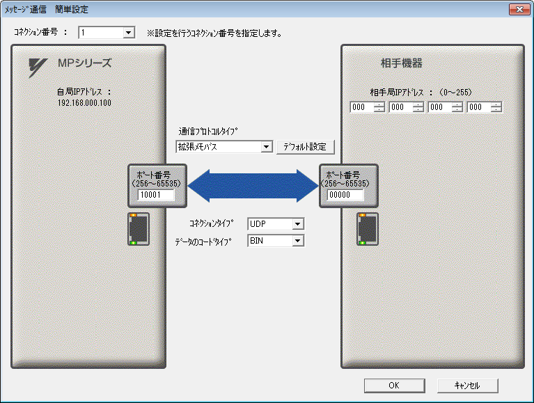
setting |
Setting contents |
Connection Number |
1 |
Communication Protocol |
Extended Membus |
MP Series: Port Number |
10001 |
Other device: Port number |
00000 |
Partner device: Partner station IP address |
000.000.000.000 |
Connection Type |
UDP |
Data Code Type |
BIN |
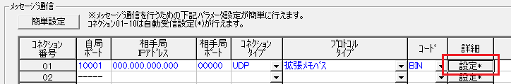
7.Click the "Set" button for the connection for which you have set parameters.
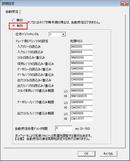
8.Enable automatic reception
9.Save the settings, close the module configuration window, and select "Online" - "Save to Flash" from the menu to write the settings.
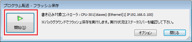
10.After writing is complete, power cycle the PLC
|
After setting the parameters, you must turn off the power to the PLC once to reflect the settings. Although a remote reset may be possible from the tool, we recommend turning off the power once to ensure that the settings are reflected. |
PC settings
Use the Server application to connect to the PLC for which you have set up communications.
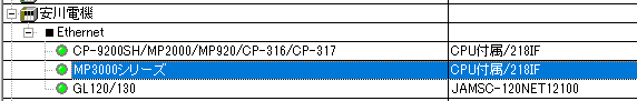
1.Right-click "Application" - "Driver" in the tree and select Add Driver.
2.Select the following units from the displayed driver list and add them:
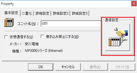
3.Open the properties of the added unit (U01) and click Communication Settings.
4.Configure the following in "PC Settings"
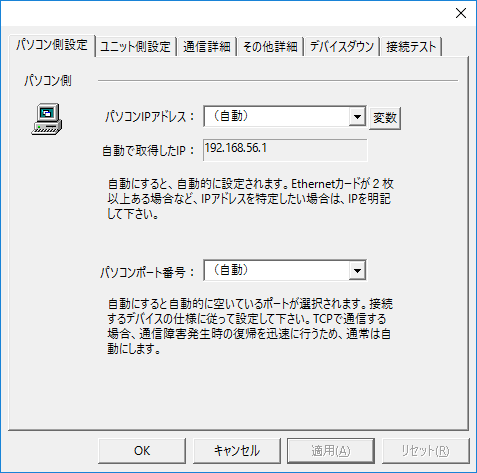
setting |
Setting contents |
Computer IP address |
Automatic |
Computer port number |
Automatic |
5.Set the following in "Unit side settings"
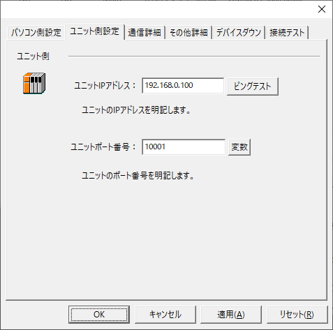
setting |
Setting contents |
Unit IP Address |
192.168.0.100 |
Unit Port Number |
10001 |
6.Select "Ping Test" to check if the ping goes through normally.
If you see a message like "Ping test is success~", the test was successful.
7.Select the protocol in "Communication Details"
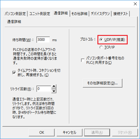
setting |
Setting contents |
protocol |
UDP (recommended) |
8.Perform a connection test to check the connection
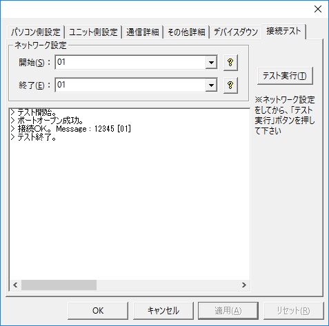
If a message such as "Connection OK" is displayed, the connection is confirmed to be OK.