overview
This article explains how to connect Yokogawa Electric devices via Ethernet.
Compatible models
List of compatible devices
Connection method |
Series/Model etc. |
Connection Unit |
Supported drivers |
Ethernet |
FA-M3 Series |
・CPU accessory port ・F3LE01-5T ・F3LE01-0T ・F3LE01-1T ・F3LE11-0T ・F3LE11-1T ・F3LE12-0T ・F3LE12-1T
|
Yokogawa Electric - Ethernet FA-M3 (When using M3R or M3V, select FA-M3R/FA-M3V)
[Connection protocol] Top Link |
Data Acquisition System GM
|
・GM10 |
ModCon-Ethernet Modbus (Modbus6 digits)
[Connection protocol] Modbus/TCP
|
|
For combinations of CPU units and link units, please check with the device manufacturer to see if the model combination is actually possible. Also, please check whether communication is possible with the protocol used when connecting with our company for that combination. |
(Reference material) Model list
series |
Model etc. |
FA-M3 Series |
F3SP71-4S, F3SP76-7S, F3SP66-4S, F3SP67-6S, F3SP21-0N, F3SP25-2N, F3SP35-5N, F3SP20-0N, F3SP30-0N, F3SP28-3N, F3SP38-6N , F3SP53-4H, F3SP58-6H, F3FP36-3N, F3SP71-4N, F3SP76-7N, F3SP28-3S, F3SP38-6S, F3SP53-4S, F3SP58-6S, F3SP59-7S, F3SP22-0S etc. |
Accessing the common area of the BASIC and CPU modules
To access the common area of a BASIC CPU module (such as F3BP20), specify as follows:
Common area word access
Specify the device as "Dxxxx". "D0001" indicates the beginning of the common area, and one device is one word. For integer type tags, one device is assigned to one tag.
Common area bit access
Specify the device as "Ixxxx". "I0001" indicates the beginning of the common area, and 1 device is 1 bit. For integer type tags, 16 devices are assigned to one tag.
Settings Dialog Details
Ethernet Common
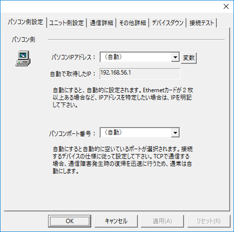
PC settings
|
•Computer IP address
•Computer port number
|
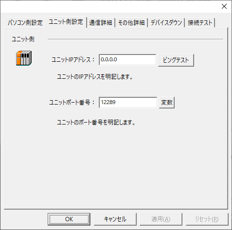
Unit side settings
|
•Unit IP Address
•Ping test
•Unit Port Number
|
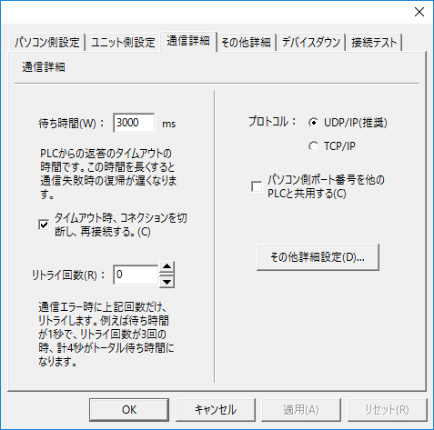
Communication details
|
•Waiting time
•Retry count
•protocol
•Share the PC port number with other PLCs
|
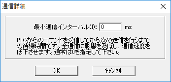
Other detailed settings
|
•Minimum Communication Interval
|