What are tags?
FA-Server supports communication with 100 types of PLCs, and can communicate with other companies' OPC servers in addition to PLC. Communication with these devices is performed via "tags." In addition to communicating with PLCs, tags can also be used for a variety of purposes, such as as a work area for internal calculations or to share data between multiple nodes via a network.
The most important point in defining tags is that all linked information can be treated equally as tags. For example, even if you have multiple different types of PLCs, such as Mitsubishi PLCs and Omron PLCs, you can treat the data on each PLC equally and flatly as a tag.
By registering and setting tags, you will be able to communicate with PLC. For example, if you want to connect to a Mitsubishi PLC and communicate with devices "D0000" and "M0000", register one tag for each device.
|
|
|
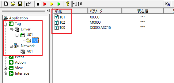
To connect to devices such as PLC, register a "unit" for each device, and then register "folders" and "tags" under it. For details on how to connect to each device, see "Device Connection Guide". |
|
Since tags actually carry out communication, they are also called "real tags" or "driver tags." |
Tag hierarchy and tag paths
Tags have a three-tiered structure: "units," "folders," and "tags."
■ Unit
A unit is created for each PLC with which communication will be performed. It defines connection setting information specific to each PLC.
■ Folder
In the
folder, you can configure the network-related settings specific to each PLC. Folders must be created under a unit. Multiple folders can be created under one unit. However, folder nesting (creating a folder under a folder) is not possible.
The
folder has two main purposes. One is when you want to group tag value update cycles by folder. The update cycle can be set for each folder, so you can manage tags that need to be updated every second separately from tags that only need to be updated once every 10 seconds. The other purpose is when setting up a daisy-chain type PLC connection. For example, some PLC models communicate with multiple PLCs from one PLC as the base point, such as in a multi-drop connection (RS-422) or MELSECNET connection (Mitsubishi PLC). In such cases, you can connect to each PLC by setting communication settings such as unit number and network number for each folder.
■ Tags
Basically, one
tag is created for each PLC device. Tags must be created under a folder. Each tag has detailed settings such as the tag name, data type, data size (word, double word, etc.), PLC device address, and filter information (type conversion, engineering value conversion, etc.).
When you register a tag connected to PLC, the tag value is automatically updated with the value from the PLC device by the communication driver. Also, when you write a value to a tag, the written value is actually written to the device on PLC via the communication driver.
Therefore, an application can know the value of the PLC device by referencing the tag value, and can rewrite the value of the PLC device by writing a value to the tag from the application.
Furthermore, tags are referenced using a format called "tag path".
The tag path format is a string consisting of a unit, folder, and tag connected with a period ".".
Example tag paths:
U01.F01.T01 |
|
Tags can also be declared as an array. |
Tag Data Type
Tags can be broadly divided into three types based on data type: bit tags, numeric tags, and string tags.
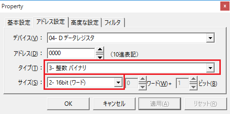
In a standard PLC, the tag type is determined by the "Type" on the "Address Settings" tab.
type |
Data Types |
0 - Bit |
Bit Tag |
1 - Integer BCD |
Numeric Tags |
2 - Integer BCD (signed) |
Numeric Tags |
3 - Integer Binary |
Numeric Tags |
4 - Integer Binary (signed) |
Numeric Tags |
5 - Single precision floating point type (IEEE) |
Numeric Tags |
6 - double precision floating point (IEEE) |
Numeric Tags |
7 - ASCII |
String tag (ASCII) |
8 - UTF-8 |
String tag (Unicode (UTF-8)) |
7 - UTF-16 |
String tag (Unicode (UTF-16)) |
Bit tags can take the value TRUE or FALSE. TRUE is ON and FALSE is OFF. Numeric tags handle numbers. String tags handle characters (including full-width characters).
|
If you want to capture bit devices as numeric tags (1/0) instead of bit tags (TRUE/FALSE), set the address setting type and size as follows: Furthermore, if you want to treat M0000 to M0015 as BCD values, you can flexibly define this by setting the type and size. For more information, see "Interpreting Devices".
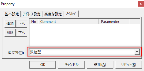
Alternatively, you can explicitly convert the tag data type in the same way as above by specifying a numeric type in the type conversion on the Filter Settings tab. For more information, see "Data Types and Type Conversions".
|
Examples of when to use tags
For example, if you set a single tag "U01.F01.T01", it can be used in a variety of situations, as shown below.
Example) IPLink client |
IPLink1.ReadVal("U01.F01.T02", value, 0)
|
Example: When connecting with DDE |
=FASERVER|U01.F01!T01
|
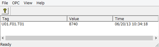
Example) As an item name for OPC |
|
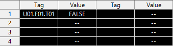
Example: In the tag monitor view |
|
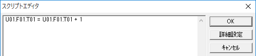
Example) Script Ver1 action |
|