Creating your first application
Here we will explain the introductory steps for communicating with PLC. The steps introduced here are roughly divided into the following two steps.
Step 1 |
Tag settings
|
Register the PLC device to communicate with as a tag. |
Step 2 |
programming
|
We will introduce examples of how to create programs for reading, writing, and monitoring (dynamic updates) using VisualBasic. |
To follow these steps, please prepare the following environment:
•FA-Engine
•VisualBasic
What is a Virtual Device?
Currently, the FA Series supports communication with 100 models, one of which is the "virtual device." A "virtual device" is an address space that simulates a PLC, and can be handled in the same way as a standard PLC device, except that it does not communicate with a specific PLC. In this manual, we will use a "virtual device" to avoid limiting the explanation to a specific PLC. Once you understand how to handle a "virtual device," you can use the same procedure to set up other standard PLCs.
Virtual Device List
device |
address |
explanation |
size |
reading |
Writing |
Input Relay |
X0000 to X9999 |
Decimal |
bit |
○ |
○ |
Output Relay |
Y0000 to Y9999 |
Decimal |
bit |
○ |
○ |
Internal Relay |
M0000 to M9999 |
Decimal |
bit |
○ |
○ |
Special Relay |
SM0000 to SM9999 (*1) |
Decimal |
bit |
○ |
○ |
Data Register |
D0000 to D9999 |
Decimal |
word |
○ |
○ |
Special Registers |
SD0000 to SD9999 (*2) |
Decimal |
word |
○ |
○ |
(※1) Special relay (SM) |
|
SM0000 On/Off every 10ms SM0001 On/Off every 50ms. SM0002 On/Off every 100ms SM0003 On/Off every 500ms
|
SM0004 On/Off every 1000ms SM0005 On/Off every 2000ms SM0006 On/Off every 3000ms SM0007 On/Off every 5000ms |
(※2) Special register (SD) |
|
SD0000 Increment every 10ms SD0001 Increment every 50ms SD0002 Increment every 100ms SD0003 Increment every 500ms |
SD0004 Increment every 1000ms SD0005 Increment every 2000ms SD0006 Increment every 3000ms SD0007 Increment every 5000ms |
SD0008 to SD0015 use the values of SD0000 to SD0007 respectively to draw a sine curve between 0 and 100.
Step 1 (Tag Settings)
Here, we will use a virtual device to simulate a PLC, so you do not need to have a real PLC at hand. If you have a PLC at hand, you can set the tag for the actual PLC.
1.Launch Tag Editor (FA-Engine6.exe)
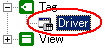
2.Right-click on "Driver" in the tree on the left and select "Add Unit".
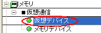
3.Select "Memory", "Virtual Communication" and "Virtual Device" and press "OK".
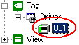
4.Right-click on "U01" and select "Add Folder"
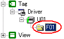
5.Right-click on "F01" and select "Add Tag"
6.Right-click on "T01" from the list on the left and select "Properties".
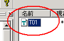
7.From the "Address Settings" tab, select "04-D Data Register" and click "OK." In the example below, D0000 (word register) is set as the numeric tag.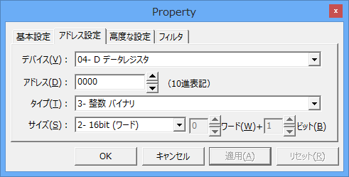
8.Save your settings
Select "Save As" from the "File" menu of the
tag editor to save the settings. Here, save it as "c:\sample.txt".
Step 2 (Programming)
Preparing your development environment
1.Launch VisualBasic
2.Paste "FA-Engine" into the form
Please follow the instructions in "Incorporate FA-Engine into Visual Basic.Net" and paste "FA-Engine" into the form.
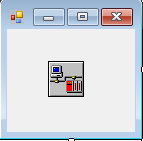
3.Property settings
Right-click on
”FA-Engine” and select “Properties” from the menu, then set it as follows.
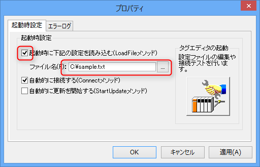
This setting will automatically load the configuration file created in "Step 1".
Implementation using ReadVal/WriteVal
1.coding
Paste two buttons and two text boxes into the form and write the following code.
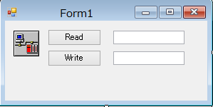
●VB.Net
Load button
Private Sub Button1_Click(ByVal sender As System.Object, ByVal e As System.EventArgs) Handles Button1.Click If Not AxEng1.ReadVal("U01.F01.T01", a) Then TextBox1.Text = "Error!" Else TextBox1.Text = a End If End Sub |
Write button
Private Sub Button2_Click(ByVal sender As System.Object, ByVal e As System.EventArgs) Handles Button2.Click If Not AxEng1.WriteVal("U01.F01.T01", TextBox2.Text) Then TextBox2.Text = "Error!" End If End SubEnd Sub |
2.Program Execution
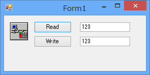
Click the Start button in Visual Basic to start the program.

Enter any number on the screen and operate the write and read buttons. Check that the displayed content changes depending on the operation.
Real-time monitor
1.coding
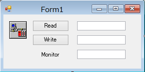
Paste a monitor text control at the bottom of the form you just created.
2.Setting the Auto Update Property
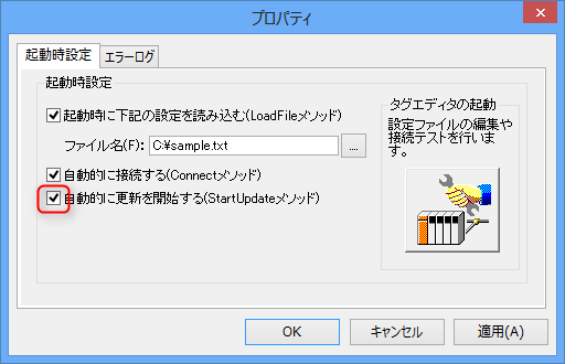
In the properties of
FA-Engine, check "Start updates automatically".
3.Added ValueChanged event
FA-Engine  Double-click and add the “ValueChanged” event.
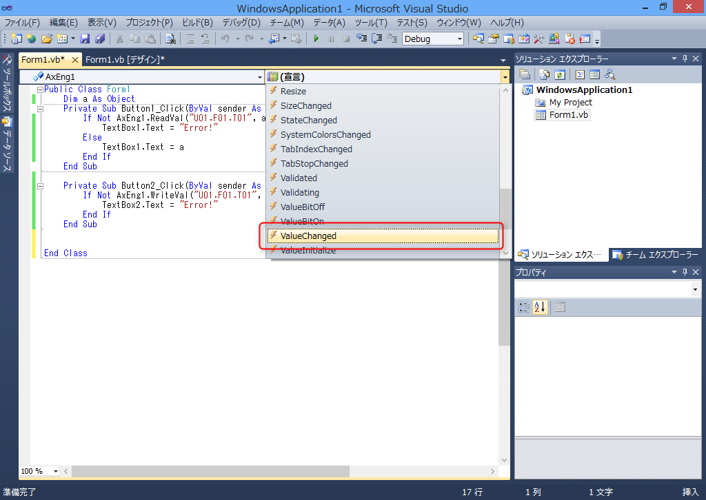
After adding the “ValueChanged” event, write the following code.
●VB.Net
Private Sub AxEng1_ValueChanged(ByVal sender As Object, ByVal e As AxFAENGINELib5._DFAEngineEvents_ValueChangedEvent) Handles AxEng1.ValueChanged Select Case e.tagPath Case "U01.F01.T01" TextBox3.Text = e.value End Select End Sub |
4.Program Execution
Click the Start button in Visual Basic to start the program.
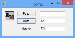
When you start the program, the current value of the tag will be displayed in the text control (Text3). Enter any numerical value on the screen and confirm that the content displayed in the text control (Text3) changes dynamically according to the value entered.