overview
This is a setting example when connecting to the FX3 series via Ethernet.
Model used
item |
Model etc. |
PLC |
FX3U-16M |
Communication Unit |
FX3U-ENET-L |
Configuration environment
item |
environment |
OS |
Windows7 Professional 64Bit |
tool |
FX3U-ENET-L Setting Tool Version 1.30 (SW1D5-FXENETL-J) |
Configuration details
item |
setting |
Setting items |
Configuration Example |
PLC side settings |
Set with tools |
IP address |
192.168.0.100 |
Port number |
8192 (2000 hex) |
||
PC settings |
Unit Settings |
IP address |
192.168.0.1 |
Port number |
8193 (hexadecimal 2001) |
||
Communication Protocol |
UDP |
||
Folder and communication test settings |
PC Number |
FF |
* Most of the settings on the computer will be adjusted to match the settings on the unit.
PLC side settings
Configure the "FX3U-16M". The configuration is done using the FX3U-ENET-L configuration tool.
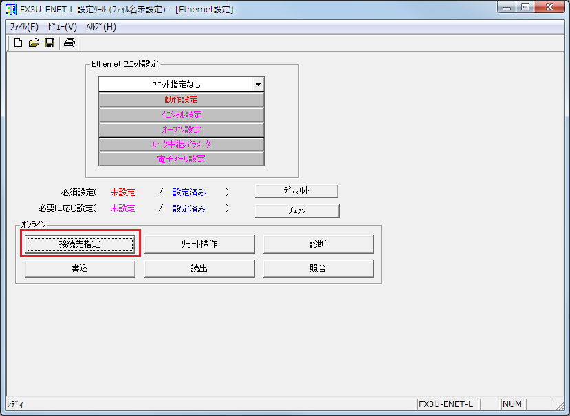
1.Start the FX3U-ENET-L setting tool
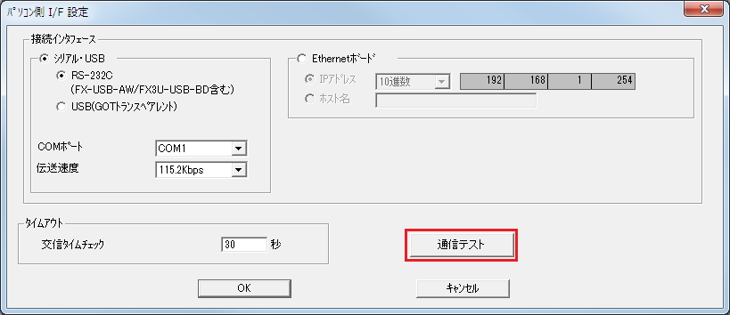
2.Click the "Specify connection" button to confirm that the connection to the FX is established.
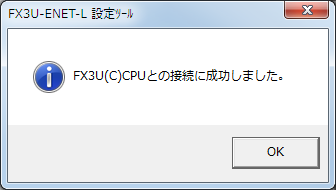
If the connection is successful, the following message will be displayed:
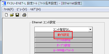
3.Click the "Operation Settings" button on the screen to display the Operation Settings screen.
4.Configure the settings as follows and click "Finish"
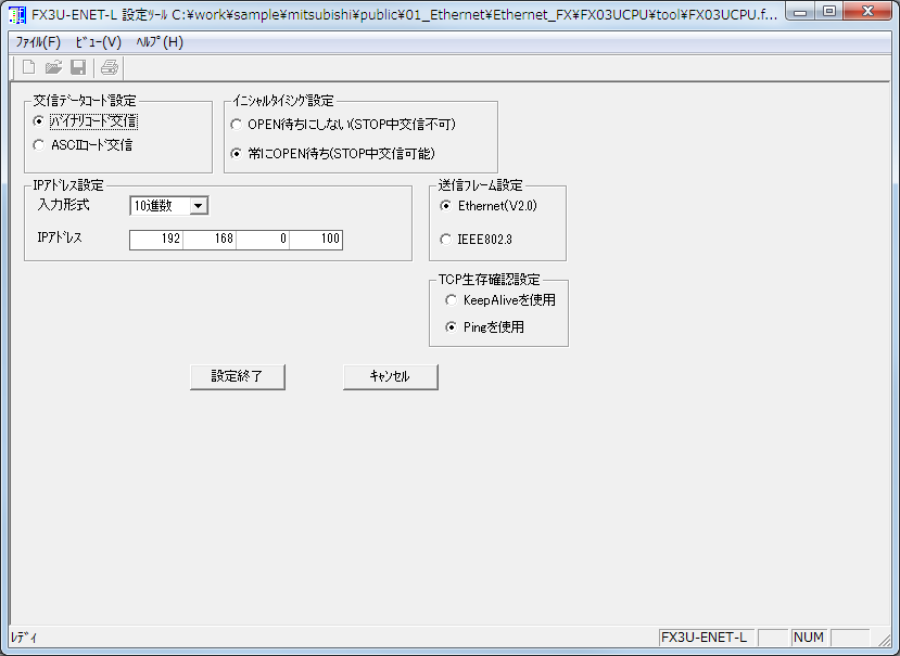
setting |
Setting contents |
Communication data code setting |
Binary Code Communication |
Initial timing setting |
Always waiting for an OPEN (communication possible during STOP) |
IP Address Settings |
192.168.0.100 |
Send frame settings |
Ethernet (V2.0) |
TCP Liveness confirmation settings |
Use Ping |
5.Press the "Open Settings" button on the screen to display the Open Settings screen.
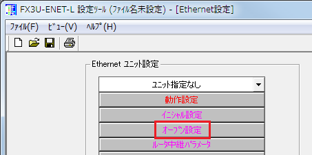
6.Configure the settings as follows and click "Finish"
Set the connection number to 3 or 4.
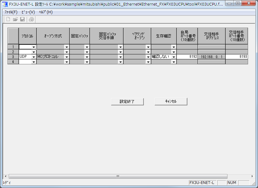
setting |
Setting contents |
protocol |
UDP |
Open Method |
MC protocol (automatically set) |
Survival confirmation |
Do not confirm |
Local station port number (decimal number) |
8192 |
IP address of the communication partner |
192.168.0.1 |
Port number of communication partner (decimal number) |
8193 |
|
When setting the port number, set it in decimal. You can also set the port number freely. The port number on the PC side and the PLC side can be the same. |
|
Connections No. 1 and 2 cannot be used because they are reserved for fixed buffer connections. Use only connection No. 3 or 4. |
7.After specifying the unit, click "Write" to write the settings to the PLC.
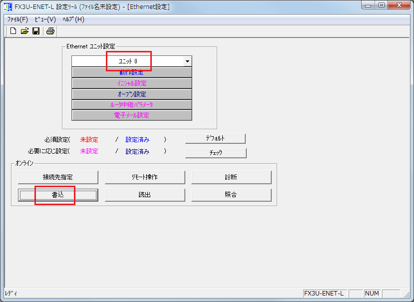
|
If the connection between the FX3U-ENET-L setting tool and the PLC is made via the Ethernet port rather than via the serial/USB port, after writing, turn the power to the PLC (CPU and FX3U-ENET-L) OFF once and then turn it on again. |
PC settings
Use the Server application to connect to the PLC for which you have set up communications.
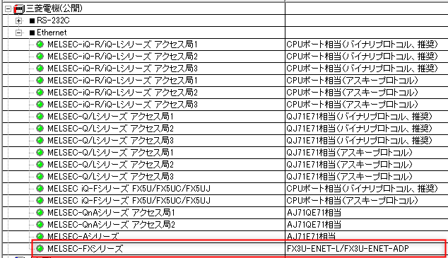
1.Right-click "Application" - "Driver" in the tree and select Add Driver.
2.Select the following units from the displayed driver list and add them:
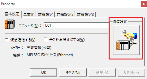
3.Open the properties of the added unit (U01) and click Communication Settings.
4.Configure the following in "PC Settings"
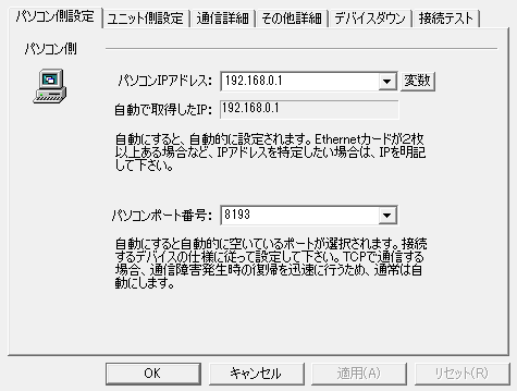
setting |
Setting contents |
Computer IP address |
192.168.0.1 |
Computer port number |
8193 (specified in decimal) |
5.Set the following in "Unit side settings"
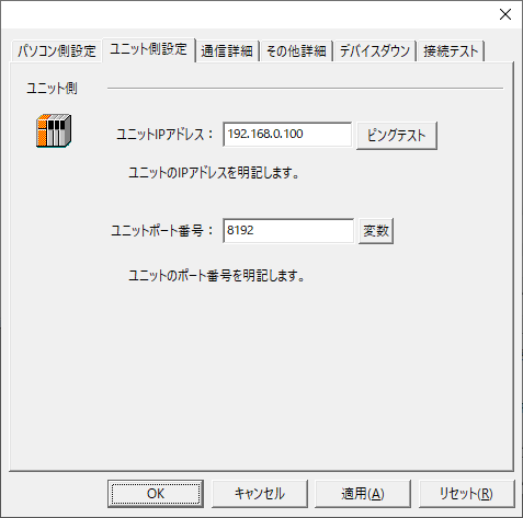
setting |
Setting contents |
Unit IP Address |
192.168.0.100 |
Unit Port Number |
8192 (specified in decimal) |
6.Select "Ping Test" to check if the ping goes through normally.
If you see a message like "Ping test is success~", the test was successful.
7.Select the protocol in "Communication Details"
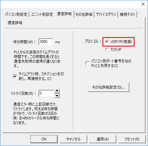
setting |
Setting contents |
protocol |
UDP (recommended) |
8.Perform a connection test to check the connection
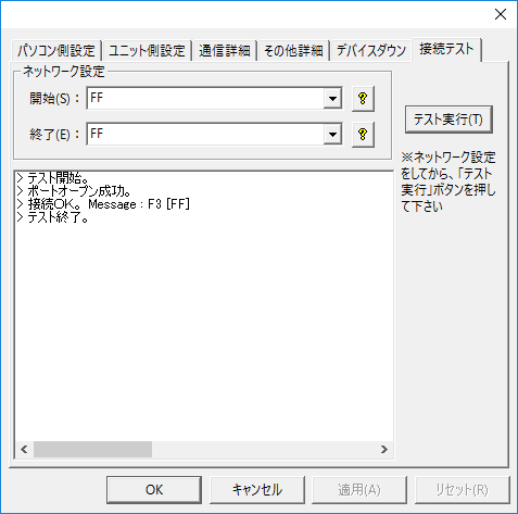
If a message such as "Connection OK" is displayed, the connection is confirmed to be OK.
|
The CPU monitoring timer can be set in the "Other detailed settings" in the unit's communication settings dialog. The CPU monitoring timer is the waiting time on the PLC side from receiving a command from the computer until returning a response to that command. If you are referencing other PLC devices via MELSECNET or CC-Link, be sure to set an appropriate time (if you set the CPU monitoring timer to 0 and the other PLC goes into a state where its power is cut off, Ethernet communication itself will be disabled). For details, refer to the PLC manual. |