overview
This is an example of Ethernet connection settings with the iQ-F series. Since the iQ-F FX5 has a built-in Ethernet port attached to the CPU, this connection example uses this built-in port to connect. Note that the iQ-F series cannot be configured with GX-Developer, so GX-Works3 is used.
Model used
item |
Model etc. |
PLC |
FX5UCPU |
Communication Unit |
CPU Attached Port |
Configuration environment
item |
environment |
OS |
Windows8 Professional 64Bit |
tool |
GX-Works3 Ver1.008J |
Configuration details
item |
setting |
Setting items |
Configuration Example |
PLC side settings |
Set with tools |
IP address |
192.168.0.100 |
Subnet Mask Pattern |
255.255.255.0 |
||
Default Router IP Address |
192.168.0.200 |
||
Communication data code setting |
Binary Code Communication |
||
RUN Write permission |
Allow |
||
protocol |
UDP |
||
Open Method |
MC Protocol |
||
Port number |
8192 (2000 hex) |
||
PC settings |
Unit Settings |
IP address |
192.168.0.1 |
Port number |
Automatic |
||
Communication Protocol |
UDP (Binary code communication) |
||
Folder and communication test settings |
Network Number |
0 |
|
PC Number |
FF |
||
Request unit I/O number |
03FF |
* Most of the settings on the computer will be adjusted to match the settings on the unit.
PLC side settings
Configure "FX5U". The settings are done using GX-Works3 etc.
1.Start GX- Works3 and create a new project.
2.Open the menu "Online" - "Connection Destination" and confirm that you can communicate with PLC.
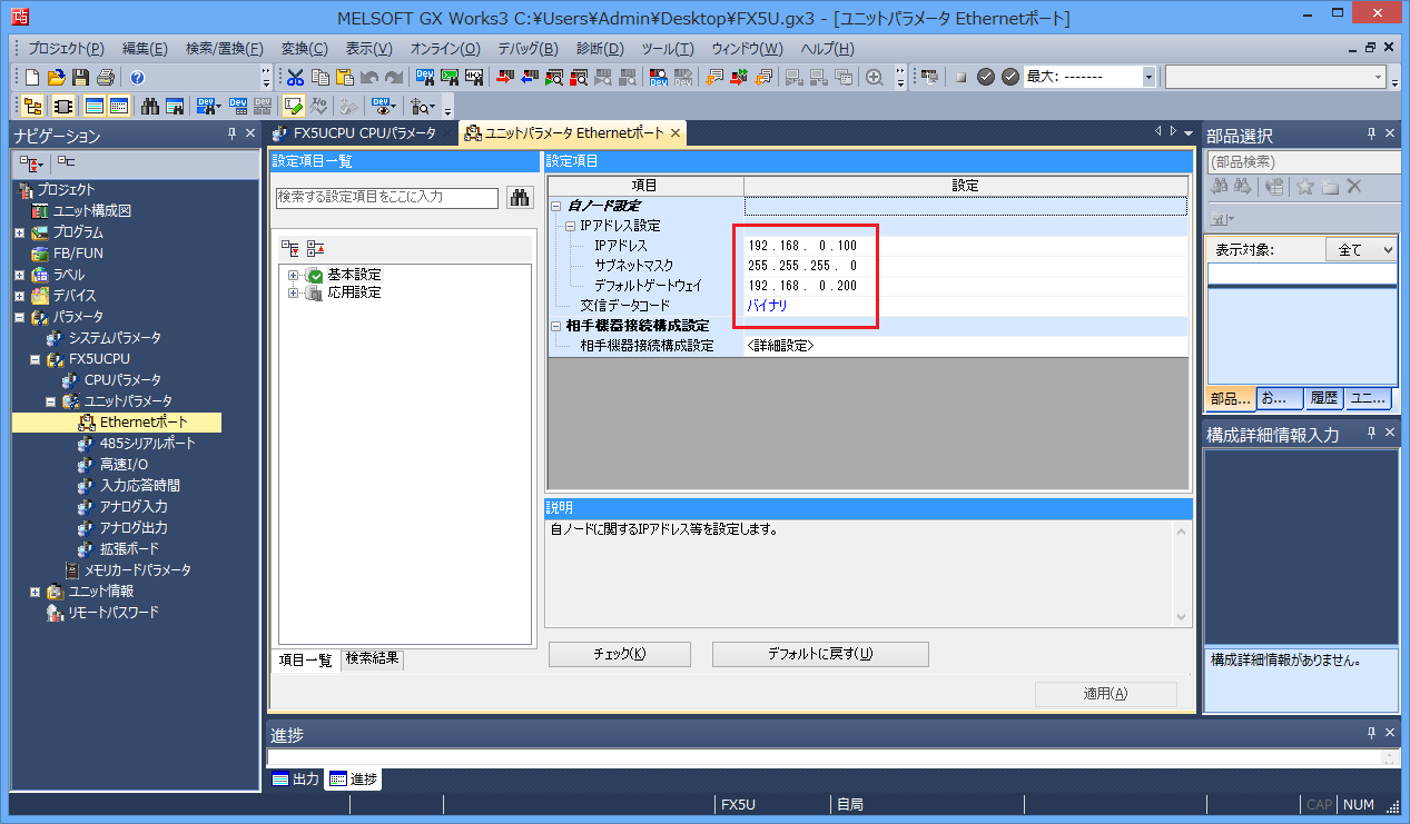
3.Double-click "Parameters" - "Connected CPU name (FX5UCPU in this case)" - "Unit parameters" - "Ethernet port" in the navigation tree and set the parameters as follows:
setting |
Setting contents |
IP address |
192.168.0.100 |
Subnet mask |
255.255.255.0 (set according to your environment) |
Default Gateway |
192.168.0.200 (set according to your environment) |
Communication data code |
binary |
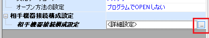
4.Select "Connection configuration settings for other device" to display the Ethernet configuration screen.
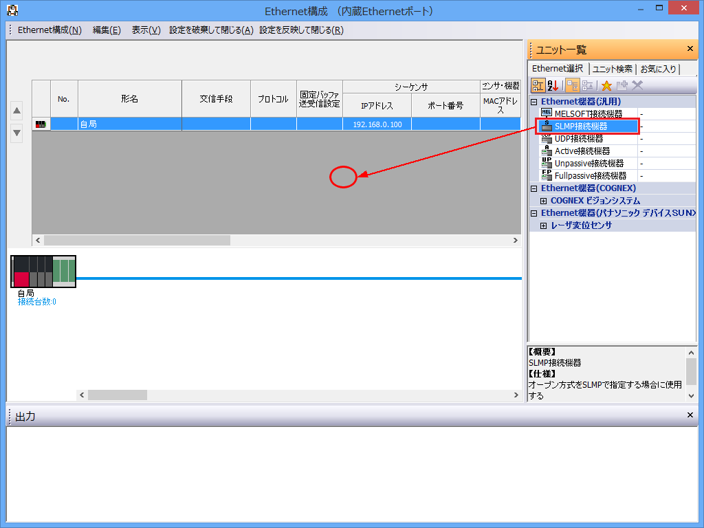
5.Add SLMP as a connected device on the Ethernet configuration screen
Select "SLMP connected device" from the unit list and add the device by dragging and dropping it onto the configuration screen.
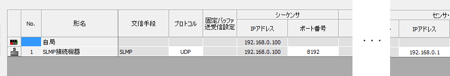
6.Once the "SLMP connected device" has been added, perform the following settings.
setting |
Setting contents |
protocol |
UDP |
Port number |
8192 (specified in decimal) |
Sensor device-IP address |
192.168.0.1 (Set the IP address of the computer) |
|
When configuring the conventional Q Series etc. with GX-Developer, the port number had to be set in hexadecimal. However, when configuring the iQ-F Series CPU with GX-Works3, please note that the port number must be specified in decimal. |
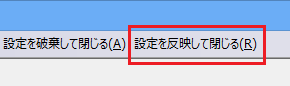
7.Click "Apply settings and close" in the menu to apply the settings and close the screen.
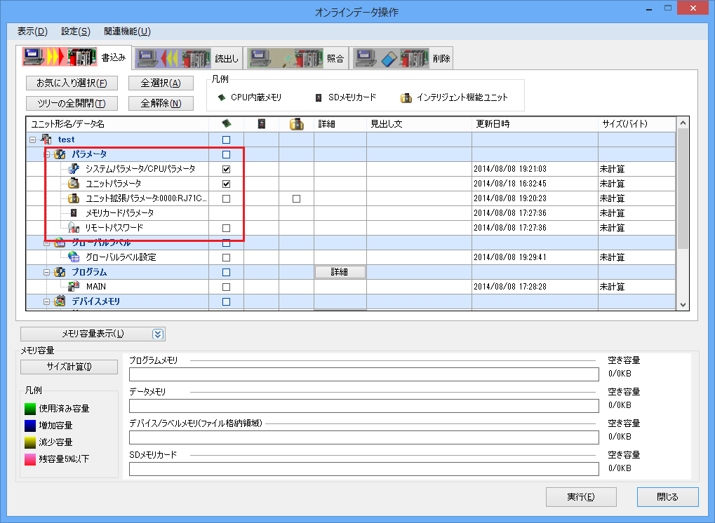
8.Write the parameters to the PLC by selecting "Online" - "Write to PLC" from the menu.
|
After setting the parameters, you must turn off the power to the PLC once to reflect the settings. Although a remote reset may be possible from the tool, we recommend turning off the power once to ensure that the settings are reflected.
|
PC settings
Use the Server application to connect to the PLC for which you have set up communications.
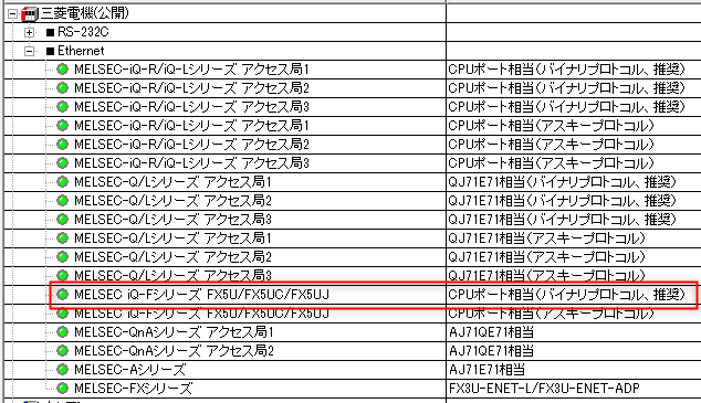
1.Right-click "Application" - "Driver" in the tree and select Add Driver.
2.Select the following units from the displayed driver list and add them:
If you want to communicate using the ASCII protocol, select the ASCII protocol.
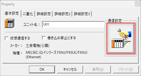
3.Open the properties of the added unit (U01) and click Communication Settings.
4.Configure the following in "PC Settings"
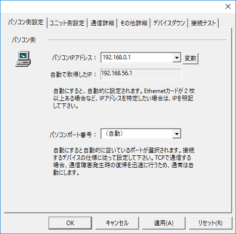
setting |
Setting contents |
Computer IP address |
192.168.0.1 |
Computer port number |
Automatic |
|
For models that directly connect to the Ethernet port, you cannot specify the port number of the connection destination, so the port number on the PC side is "Automatic". |
5.Set the following in "Unit side settings"
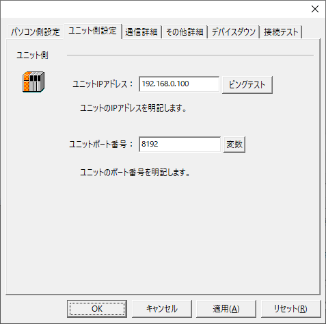
setting |
Setting contents |
Unit IP Address |
192.168.0.100 |
Unit Port Number |
8192 (specified in decimal) |
6.Select "Ping Test" to check if the ping goes through normally.
If you see a message like "Ping test is success~", the test was successful.
7.Select the protocol in "Communication Details"
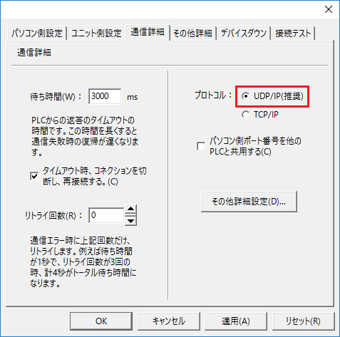
setting |
Setting contents |
protocol |
UDP (recommended) |
8.Perform a connection test to check the connection
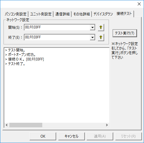
If a message such as "Connection OK" is displayed, the connection is confirmed to be OK.
|
The CPU monitoring timer can be set in the "Other detailed settings" in the unit's communication settings dialog. The CPU monitoring timer is the waiting time on the PLC side from receiving a command from the computer until returning a response to that command. If you are referencing other PLC devices via MELSECNET or CC-Link, be sure to set an appropriate time (if you set the CPU monitoring timer to 0 and the other PLC goes into a state where its power is cut off, Ethernet communication itself will be disabled). For details, refer to the PLC manual. |