overview
This is a connection example with Yokogawa Electric's GM10. This is a setting example for an Ethernet connection using Modbus/TCP.
Model used
item |
Model etc. |
device |
GM10 |
Communication Unit |
Ports included with the unit |
Configuration environment
item |
environment |
OS |
Windows10 Pro 64Bit |
tool |
IP Address Setting Tool Web browser (Microsoft Edge, etc.) |
Configuration details
item |
setting |
Setting items |
Configuration Example |
Device settings |
Set with tools |
IP address |
192.168.1.1 |
Subnet mask |
255.255.255.0 |
||
Port number |
502 |
||
PC settings |
Unit Settings |
IP address |
192.168.0.1 |
Port number |
Automatic |
||
Communication Protocol |
TCP (UDP cannot be specified) |
||
Folder Settings |
Unit ID |
255 |
* Most of the settings on the computer will be adjusted to match the settings on the unit.
Device settings
Configure the "GM10". The settings are done using an IP address setting tool and a web browser such as Microsoft Edge.
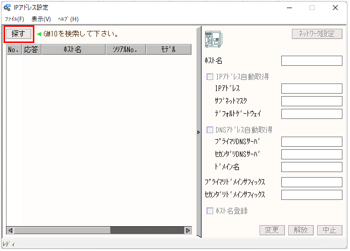
1.Start the IP address setting tool and click "Search".
|
If multiple network adapters are connected, the device cannot be found. In such cases, you will need to disable all adapters other than the one connected to the device using the following method. - Remove everything except the network adapter connected to the device. - Disable all network adapters in the OS settings except for the one connected to the device, etc.
|
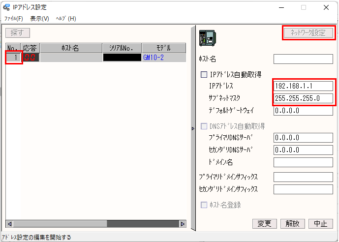
2.Select the target device, click "Network Settings" and set as follows
setting |
Setting contents |
IP address |
192.168.1.1 |
Subnet mask |
255.255.255.0 |
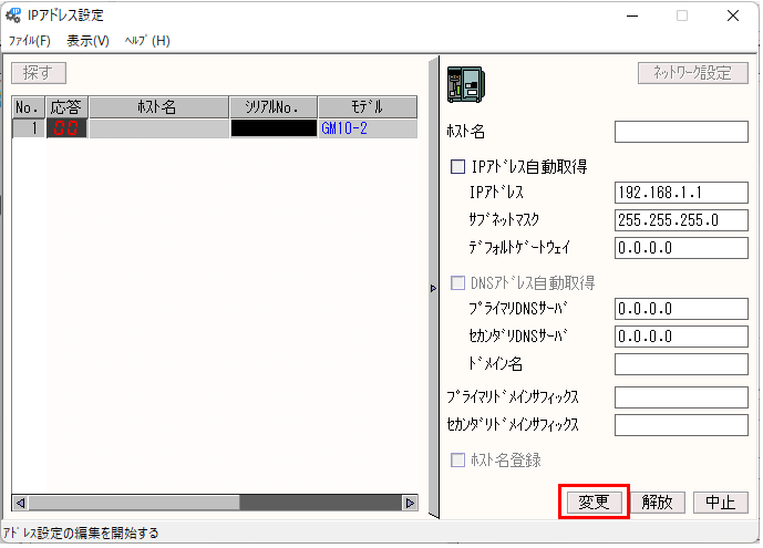
3.Click "Change" and exit the tool
|
The IP address cannot be changed if the GM (firmware version R2.03.01 or later) is in the following state: If changing the IP address fails, the message "Address setting failed" is displayed. -The security function setting is set to Communication [Login]. - The advanced security function (additional specification, /AS) is set to [On] and recording is in progress.
|
4.Access the IP address of the target device from a WEB browser
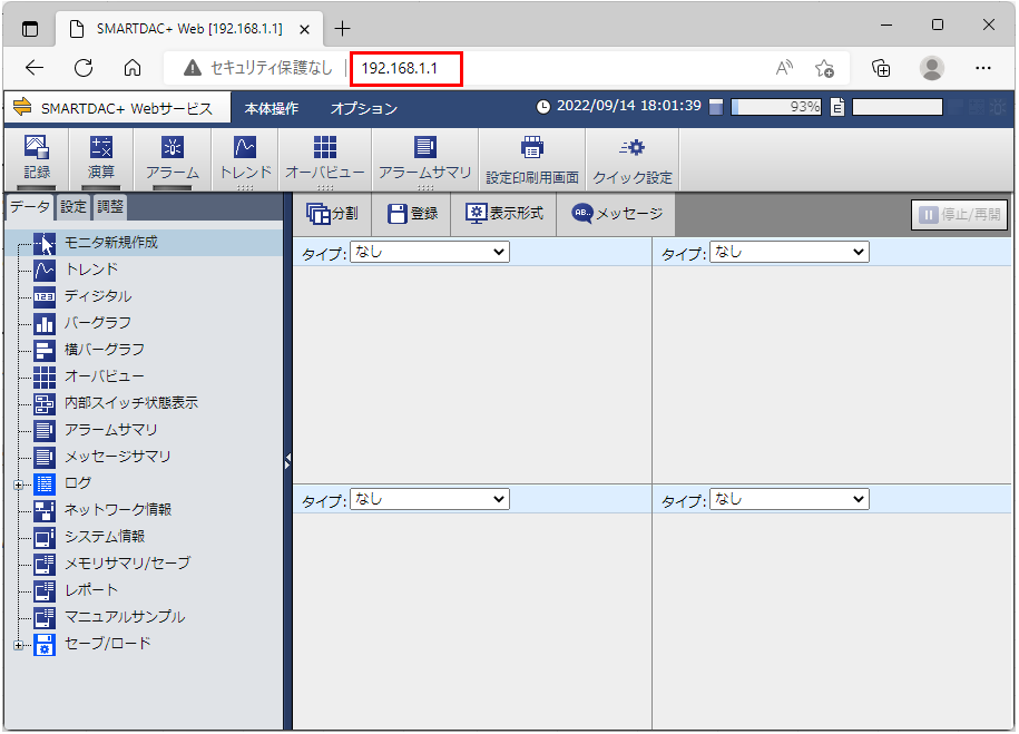
5.Open "Settings" tab - "Communication (Ethernet) Settings" - "Server Settings Server List"

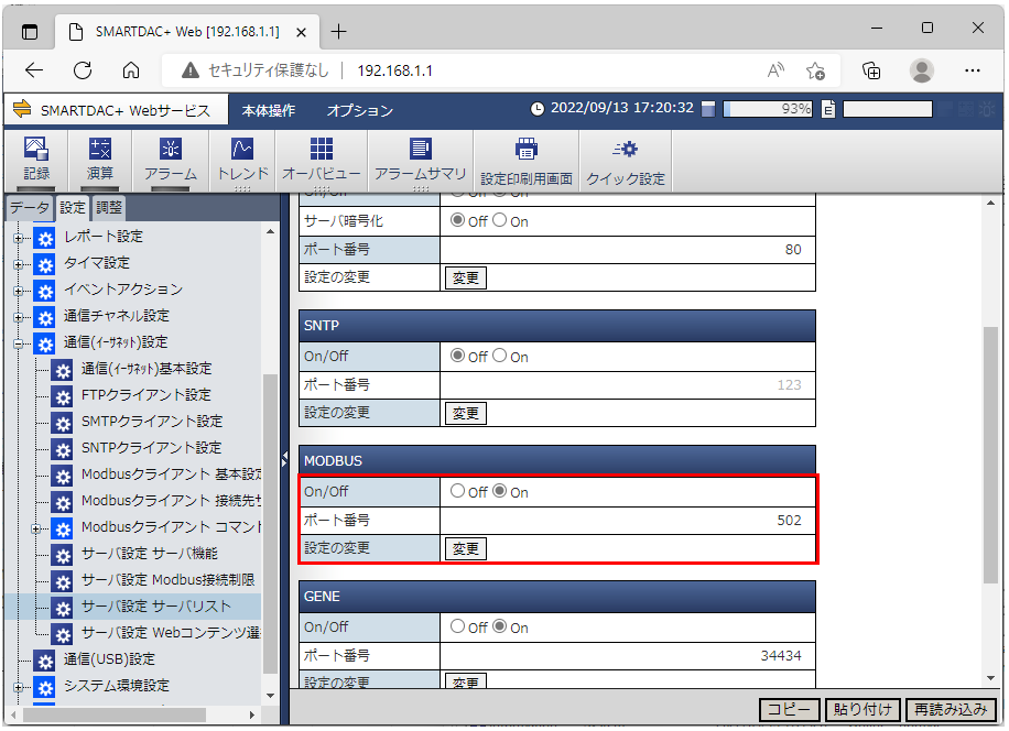
6.Set MODBUS as follows and click "Change"
setting |
Setting contents |
On/Off |
Select "On" |
Port number |
502 |
PC settings
Use the Server application to connect to the device for which you have set up communications.
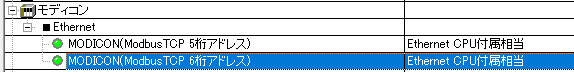
1.Right-click "Application" - "Driver" in the tree and select Add Driver.
2.Select the following units from the displayed driver list and add them:
3.Open the properties of the added unit (U01) and click Communication Settings.
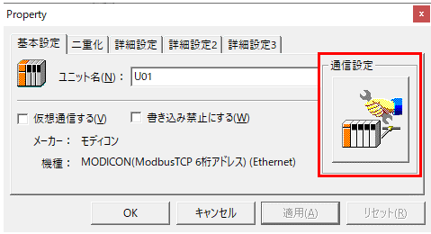
4.Configure the following in "PC Settings"
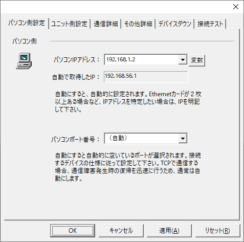
setting |
Setting contents |
Computer IP address |
192.168.1.2 |
Computer port number |
(Automatic) |
5.Set the following in "Unit side settings"
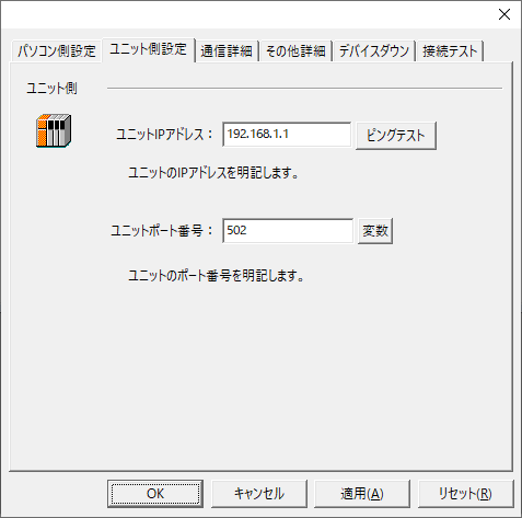
setting |
Setting contents |
Unit IP Address |
192.168.1.1 |
Unit Port Number |
502 |
6.Select "Ping Test" to check if the ping goes through normally.
If you see a message such as "Ping test is success~", the test was successful.
7.Specify "255" for "Start" and "End" in the network settings, perform a connection test, and confirm the connection.
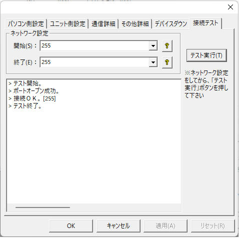
If a message such as "Connection OK" is displayed, the connection is confirmed.
|
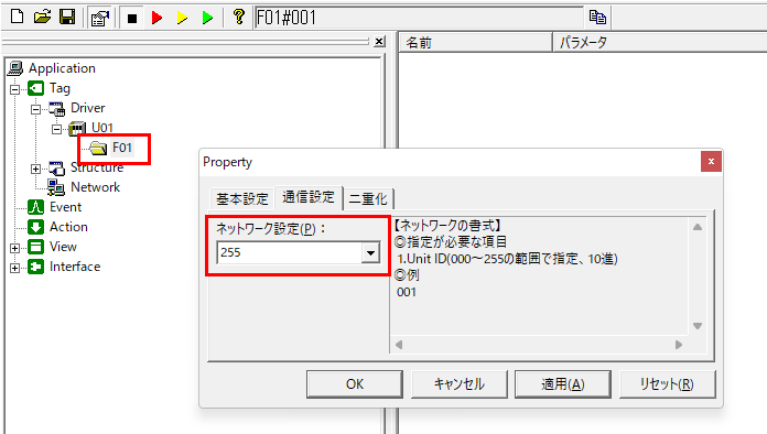
The GM10 Unit ID is fixed at "255", so specify "255" as the parameter. |
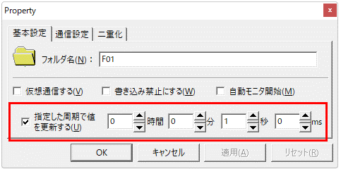
Folder settings
The GM10 Unit ID is fixed at "255", so specify "255" in the communication settings for the folder you want to add under the unit.
Update cycle
We have confirmed that if the update cycle is set to longer than a certain period of time (30 seconds or more), TCP/IP communication is disconnected from the device.
Therefore, make sure to specify an update interval shorter than 30 seconds.
Please note that this behavior depends on the device specifications and may change in the future. Please contact Yokogawa Electric for details.
Mapping and tagging
The mapping on the GM10 side during Modbus/TCP communication is as follows:
|
The contents on this page are excerpts from the GM manual. For details, please refer to the device manual. |
coil
kinds |
|
number |
Type |
Input/Output Channels |
Input data |
00001 to 00500 |
Bit |
Status Information |
00501 to 01000 |
|
|
Communication Channels |
Calculation Data |
01001 to 01500 |
|
Status Information |
01501 to 02000 |
|
|
Internal Switch |
|
02001 to 02100 |
|
|
The writable areas of the coil are as follows: - Communication channel communication data (01001 to 01500) - Internal switches (02001 to 02100) *The type of switch must be specified in the manual If you write to any other area, a communication error will occur. |
Input relay (input status)
kinds |
|
number |
Type |
Input/Output Channels |
Input data |
100001 to 100500 |
Bit |
Status Information |
100501 to 101000 |
|
|
Communication Channels |
Calculation Data |
101001 to 101200 |
|
Status Information |
101501 to 101700 |
|
Input Register
unit |
kinds |
|
number |
Type |
Main Unit |
Input/Output Channels |
Input/Output Data |
300001 to 301000 |
Signed 32-bit integer type |
|
301001 to 302000 |
32-bit floating-point type |
||
|
302001 to 302500 |
Signed 16-bit integer type |
||
Status Information |
302501 to 303000 |
Signed 16-bit integer type |
||
Input/Output Channels |
Input/Output Data |
304201 to 304400 |
Signed 32-bit integer type |
|
(Continuous area) |
|
304401 to 304500 |
32-bit floating-point type |
|
Status Information |
304501 to 304600 |
Signed 16-bit integer type |
||
Calculation Channel |
Calculation Data |
305001 to 305200 |
Signed 32-bit integer type |
|
(A001 to A100) |
|
305201 to 305400 |
32-bit floating-point type |
|
|
305401 to 305500 |
Signed 16-bit integer type |
||
Status Information |
305501 to 305600 |
Signed 16-bit integer type |
||
Calculation Channel |
Calculation Data |
306001 to 306200 |
Signed 32-bit integer type |
|
(A101 to A200) |
|
306201 to 306400 |
32-bit floating-point type |
|
|
306401 to 306500 |
Signed 16-bit integer type |
||
Status Information |
306501 to 306600 |
Signed 16-bit integer type |
||
Device Status |
|
308001 to 308007 |
Signed 16-bit integer type |
|
Subunits |
Unit 1 |
Input/Output Data |
310001 to 311000 |
Signed 32-bit integer type |
Input/Output Channels |
|
311001 to 312000 |
32-bit floating-point type |
|
|
312001 to 312500 |
Signed 16-bit integer type |
||
Status Information |
312501 to 313000 |
Signed 16-bit integer type |
||
Unit 2 |
Input/Output Data |
315001 to 316000 |
Signed 32-bit integer type |
|
Input/Output Channels |
|
316001 to 317000 |
32-bit floating-point type |
|
|
317001 to 317500 |
Signed 16-bit integer type |
||
Status Information |
317501 to 318000 |
Signed 16-bit integer type |
||
Unit 3 |
Input/Output Data |
320001 to 321000 |
Signed 32-bit integer type |
|
Input/Output Channels |
|
321001 to 322000 |
32-bit floating-point type |
|
|
322001 to 322500 |
Signed 16-bit integer type |
||
Status Information |
322501 to 323500 |
Signed 16-bit integer type |
||
Unit 4 |
Input/Output Data |
325001 to 326000 |
Signed 32-bit integer type |
|
Input/Output Channels |
|
326001 to 327000 |
32-bit floating-point type |
|
|
327001 to 327500 |
Signed 16-bit integer type |
||
Status Information |
327501 to 328000 |
Signed 16-bit integer type |
||
Unit 5 |
Input/Output Data |
330001 to 331000 |
Signed 32-bit integer type |
|
Input/Output Channels |
|
331001 to 332000 |
32-bit floating-point type |
|
|
332001 to 332500 |
Signed 16-bit integer type |
||
Status Information |
332500 to 333000 |
Signed 16-bit integer type |
||
Unit 6 |
Input/Output Data |
335001 to 336000 |
Signed 32-bit integer type |
|
Input/Output Channels |
|
336001 to 337000 |
32-bit floating-point type |
|
|
337001 to 337500 |
Signed 16-bit integer type |
||
Status Information |
337501 to 338000 |
Signed 16-bit integer type |
Holding Register
unit |
kinds |
|
number |
Type |
Main Unit |
Input/Output Channels |
Input/Output Data |
400001 to 401000 |
Signed 32-bit integer type |
|
401001 to 402000 |
32-bit floating-point type |
||
|
402001 to 402500 |
Signed 16-bit integer type |
||
Status Information |
402501 to 403000 |
Signed 16-bit integer type |
||
Input/Output Channels |
Input/Output Data |
404001 to 404200 |
Signed 32-bit integer type |
|
(Continuous area) |
|
404201 to 404400 |
32-bit floating-point type |
|
|
404401 to 404500 |
Signed 16-bit integer type |
||
Status Information |
404501 to 404600 |
Signed 16-bit integer type |
||
Communication Channels |
Communication Data |
405001 to 406000 |
Signed 32-bit integer type |
|
|
406001 to 407000 |
32-bit floating-point type |
||
|
407001 to 407500 |
Signed 16-bit integer type |
||
Status Information |
407501 to 408000 |
Signed 16-bit integer type |
||
Internal Switch |
|
408001 to 408100 |
Signed 16-bit integer type |
|
Main unit operation settings |
|
409001 to 410000 |
Signed 16-bit integer type |
|
Subunits |
Unit 1 |
Input/Output Data |
410001 to 411000 |
Signed 32-bit integer type |
Input/Output Channels |
|
411001 to 412000 |
32-bit floating-point type |
|
|
412001 to 412500 |
Signed 16-bit integer type |
||
Status Information |
412501 to 413000 |
Signed 16-bit integer type |
||
Unit 2 |
Input/Output Data |
415001 to 416000 |
Signed 32-bit integer type |
|
Input/Output Channels |
|
416001 to 417000 |
32-bit floating-point type |
|
|
417001 to 417500 |
Signed 16-bit integer type |
||
Status Information |
417501 to 418000 |
Signed 16-bit integer type |
||
Unit 3 |
Input/Output Data |
420001 to 421000 |
Signed 32-bit integer type |
|
Input/Output Channels |
|
421001 to 422000 |
32-bit floating-point type |
|
|
422001 to 422500 |
Signed 16-bit integer type |
||
Status Information |
422501 to 423000 |
Signed 16-bit integer type |
||
Unit 4 |
Input/Output Data |
425001 to 426000 |
Signed 32-bit integer type |
|
Input/Output Channels |
|
426001 to 427000 |
32-bit floating-point type |
|
|
427001 to 427500 |
Signed 16-bit integer type |
||
Status Information |
427501 to 428000 |
Signed 16-bit integer type |
||
Unit 5 |
Input/Output Data |
430001 to 431000 |
Signed 32-bit integer type |
|
Input/Output Channels |
|
431001 to 432000 |
32-bit floating-point type |
|
|
432001 to 432500 |
Signed 16-bit integer type |
||
Status Information |
432501 to 433000 |
Signed 16-bit integer type |
||
Unit 6 |
Input/Output Data |
435001 to 436000 |
Signed 32-bit integer type |
|
Input/Output Channels |
|
436001 to 437000 |
32-bit floating-point type |
|
|
437001 to 437500 |
Signed 16-bit integer type |
||
Input/Output Data |
437501 to 438000 |
Signed 16-bit integer type |
||
Channel Properties |
Each channel information |
Channel Properties |
440001 to 465000 |
Signed 16-bit integer type |
|
The writable areas of the holding register are as follows: - Communication channel communication data (405001 to 407500) - Internal switches (408001 to 408100) *The type of switch must be specified in the manual If you write to any other area, a communication error will occur. |
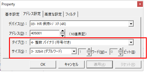
Please set the tags according to the format specified on the GM side.
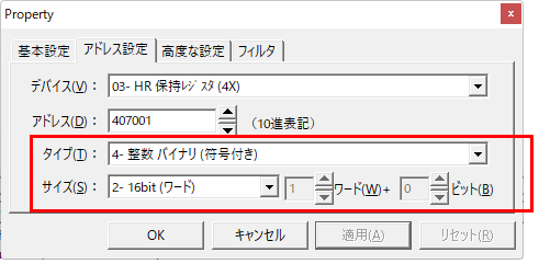
Example: When referencing holding register 405001 (signed 32-bit integer type)
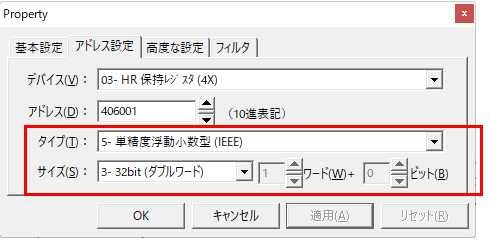
Example: When referencing holding register 406001 (32-bit floating-point type)
Example: When referencing holding register 407001 (signed 16-bit integer type)