overview
This is a connection example with Keyence's NQ series. This is a setting example for Ethernet connection using Modbus/TCP.
Model used
item |
Model etc. |
device |
NQ-MP8L |
Local Devices |
FD-Q10C (Clamp-on type flow sensor) |
Communication Unit |
Ports included with the unit |
Configuration environment
item |
environment |
OS |
Windows10 Pro 64Bit |
Configuration details
item |
setting |
Setting items |
Configuration Example |
Device settings |
Set with the switch on the main unit |
IP address |
192.168.0.100 |
Subnet mask |
255.255.255.0 |
||
Default Gateway |
192.168.0.1 |
||
Port number |
502 (fixed) |
||
PC settings |
Unit Settings |
IP address |
192.168.0.1 |
Port number |
Automatic |
||
Communication Protocol |
TCP (UDP cannot be specified) |
* Most of the settings on the computer will be adjusted to match the settings on the unit.
|
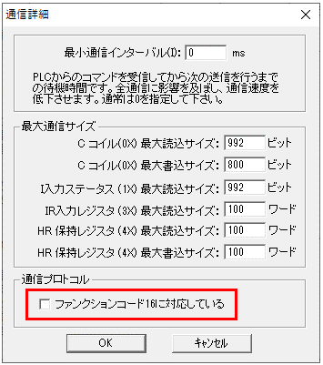
The only device supported by the NQ series is HR. Also, writing to the NQ series HR is only supported by function code 06. To use function code 06, uncheck the following settings in the Server application's communication details/other detailed settings.
|
|
Modbus/TCP is used for communication with the NQ series. Therefore, the models that can communicate are limited to those that can use Modbus/TCP (such as NQ-MP8L). For details on the applicable models, please refer to the device's manual. |
Device settings
Configure the settings for the "NQ-MP8L". Settings are made using the switch on the device and the NQ Sensor Monitor.
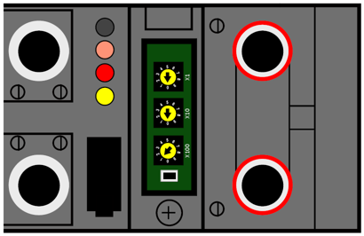
1.Set the IP address using the rotary switch on the unit
setting |
Setting contents |
Rotary Switch x100 |
1 |
Rotary switch x10 |
0 |
Rotary switch x1 |
0 |
|
The value specified by the switch will be assigned to the following "xxx" and used for operation.
・IP address: 192.168.0.xxx -Subnet mask: 255.255.255.0 ・Default gateway: 192.168.0.1
If all rotary switches are set to 0, the IP address will be "192.168.0.250".
|
|
If you are using a model that does not have a switch on the main unit, you must set the IP address using the setting tool "NQ Sensor Monitor." Also, if you want to set the IP address of the NQ-MP8L from the setting tool, set the rotary switch to "600" (PGM-DHCP). |
PC settings
Use the Server application to connect to the device for which you have set up communications.
1.Right-click "Application" - "Driver" in the tree and select Add Driver.
2.Select the following units from the displayed driver list and add them:
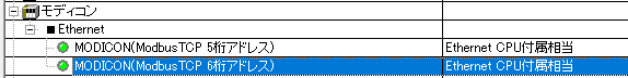
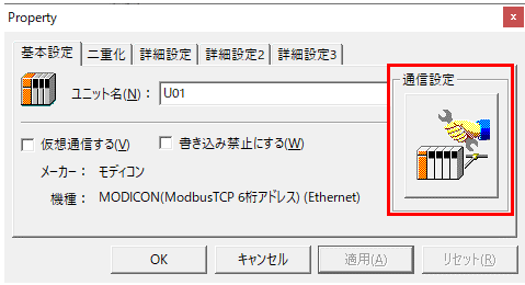
3.Open the properties of the added unit (U01) and click Communication Settings.
4.Configure the following in "PC Settings"
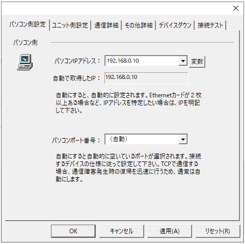
setting |
Setting contents |
Computer IP address |
192.168.0.10 |
Computer port number |
Automatic |
5.Set the following in "Unit side settings"
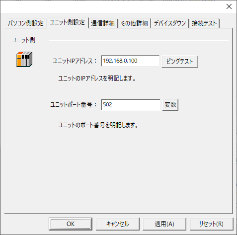
setting |
Setting contents |
Unit IP Address |
192.168.0.100 |
Unit Port Number |
502 |
6.Select "Ping Test" to check if the ping goes through normally.
If you see a message like "Ping test is success~", the test was successful.
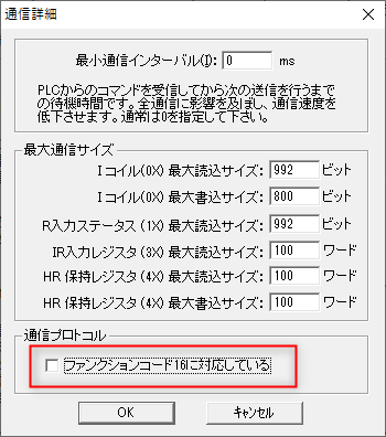
7.Click "Other detailed settings" under "Communication details"
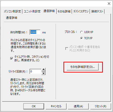
8.Uncheck "Supports function code 16" and press the "OK" button.
|
Normally, function code 16 is used to write to an HR device, but by unchecking the above, writing will be performed using function code 6. This model only supports writing function code 6, so this setting must be unchecked. |
9.Perform a connection test to check the connection
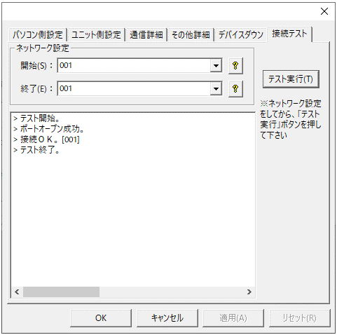
If a message such as "Connection OK" is displayed, the connection is confirmed.
About tag settings
The data output format varies depending on the local device and settings, so you need to configure the tag to best suit your situation.
As an example, we will introduce a configuration example for connecting a Keyence clamp-on flow sensor (FD-Q10C) to port 1 of the NQ-MP8L to obtain the instantaneous flow rate.
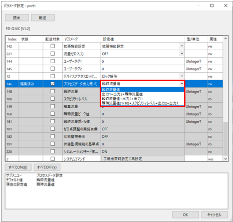
The output format of the FD-Q10C process data can be selected from the following four types.
- Instantaneous flow rate value
・Output 1 + Output 2 + Instantaneous flow rate value
・Instantaneous flow rate value + output 2 + output 1
・Instantaneous flow rate value (1/10) + stability level + output 2 + output 1
The output format can be selected using the configuration tool "NQ Sensor Monitor".
Instantaneous flow rate
・Process data output format: 0 = Instantaneous flow rate (default value)
Bit15 |
Bit14 |
Bit13 |
Bit12 |
Bit11 |
Bit10 |
Bit9 |
Bit8 |
Bit7 |
Bit6 |
Bit5 |
Bit4 |
Bit3 |
Bit2 |
Bit1 |
Bit0 |
0 |
0 |
Instantaneous flow rate value (unit: FD-Q10C: 0.01, other than FD-Q10C: 0.1) |
|||||||||||||
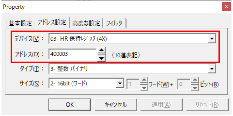
・Address setting
When port 1 is connected, the instantaneous flow rate value is stored in HR400003, so refer to this address.
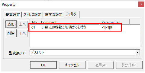
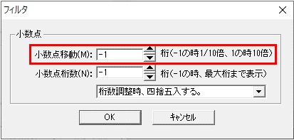
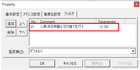
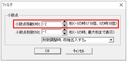
·filter
Since the unit is 0.01, specify "Move decimal point and truncate" in the filter and set it to 1/100 times.
|
|
Output 1 + Output 2 + Instantaneous flow rate value
Process data output format: 1 = Output2 + Output1 + Instantaneous flow rate
Bit15 |
Bit14 |
Bit13 |
Bit12 |
Bit11 |
Bit10 |
Bit9 |
Bit8 |
Bit7 |
Bit6 |
Bit5 |
Bit4 |
Bit3 |
Bit2 |
Bit1 |
Bit0 |
Output 1 |
Output 2 |
Instantaneous flow rate value (unit: FD-Q10C: 0.01, other than FD-Q10C: 0.1) |
|||||||||||||
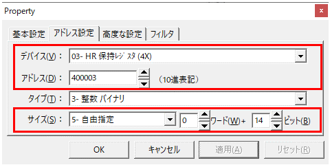
・Address setting
When port 1 is connected, the instantaneous flow rate value is stored in HR400003, so refer to this address.
The size can be freely set to handle 14 bits of data.
·filter
Since the unit is 0.01, specify "Move decimal point and truncate" in the filter and set it to 1/100 times.
|
|
Instantaneous flow rate value + output 2 + output 1
Process data output format: 2 = Instantaneous flow rate + Output2 + Output1
Bit15 |
Bit14 |
Bit13 |
Bit12 |
Bit11 |
Bit10 |
Bit9 |
Bit8 |
Bit7 |
Bit6 |
Bit5 |
Bit4 |
Bit3 |
Bit2 |
Bit1 |
Bit0 |
Instantaneous flow rate value (unit: FD-Q10C: 0.01, other than FD-Q10C: 0.1) |
Output 2 |
Output 1 |
|||||||||||||
・Address setting
When port 1 is connected, the instantaneous flow rate value is stored in HR400003, so refer to this address.
The bit starting position is set to 2 (@2 is added), and the size can be freely set to handle 14 bits of data.
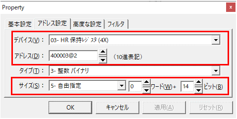
·filter
Since the unit is 0.01, specify "Move decimal point and truncate" in the filter and set it to 1/100 times.
|
|
Instantaneous flow rate value (1/10) + stability level + output 2 + output 1
Process data output format: 3 = Instantaneous flow rate (one tenth) + Stability level + Output2 + Output1
Bit15 |
Bit14 |
Bit13 |
Bit12 |
Bit11 |
Bit10 |
Bit9 |
Bit8 |
Bit7 |
Bit6 |
Bit5 |
Bit4 |
Bit3 |
Bit2 |
Bit1 |
Bit0 |
Instantaneous flow rate value (1/10) (unit: FD-Q10C: 0.1, other than FD-Q10C: 1) |
0 |
Stability Level |
Output 2 |
Output 1 |
|||||||||||
・Address setting
When port 1 is connected, the instantaneous flow rate value is stored in HR400003, so refer to this address.
The bit starting position is set to 6 (@6 is added), and the size can be freely set to handle 10 bits of data.
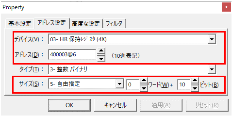
·filter
Since the unit is 0.1, specify "Move decimal point and truncate" in the filter and set it to 1/10 times.
|
|