overview
This is a configuration example for connecting to the WL40/IT series via Ethernet.
Model used
item |
Model etc. |
Wireless base station |
WL40EW2 |
Indicator Light |
IT60SW6 |
Configuration environment
item |
environment |
OS |
Windows7 Professional 64Bit |
Indicator Light Setting Tool |
ITCFG Ver 1.5.32 |
Configuration details
item |
setting |
Setting items |
Configuration Example |
Wireless router settings |
WEBSettings in browser |
IP address |
192.168.0.1 |
Subnet mask |
255.255.255.0 |
||
Port number |
502 |
||
Indicator light settings |
Set with tools |
PAN ID |
0001 |
Channel Number |
1 |
||
Short Address |
0001 |
||
Network Name |
MH920 |
||
Encryption Key |
Any value |
||
PC settings |
Unit Settings |
IP address |
192.168.0.10 |
Port number |
502 |
||
Folder and communication test settings |
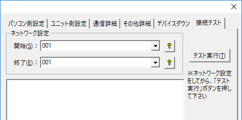
Node Number |
001 |
Special notes for the WL40/IT series
IT Series Device Mapping
The device mapping for the IT series is as follows:
Input/Output
Device (Address) |
item |
Setting Value |
Coil (00001) |
Lamp 1 |
0: off 1: on |
Coil (00002) |
Lamp 2 |
0: off 1: on |
Coil (00003) |
Lamp 3 |
0: off 1: on |
Coil (00004) |
Lamp 4 |
0: off 1: on |
Coil (00005) |
Lamp 5 |
0: off 1: on |
Coil (00006) |
buzzer |
0: Stop 1: Continuous |
Coil (00007) |
- |
- |
Coil (00008) |
- |
- |
Coil (00009) |
Lamp 1 |
0: off 1: on |
Coil (00010) |
Lamp 2 |
0: off 1: on |
Coil (00011) |
Lamp 3 |
0: off 1: on |
Coil (00012) |
Lamp 4 |
0: off 1: on |
Coil (00013) |
Lamp 5 |
0: off 1: on |
Coil (00014) |
buzzer |
0: Stop 1: Continuous |
Coil (00015) |
- |
- |
Coil (00016) |
- |
- |
·input
Device (Address) |
item |
Setting Value |
Input Status (10001) |
Lamp 1 |
0: off 1: on |
Input Status (10002) |
Lamp 2 |
0: off 1: on |
Input Status (10003) |
Lamp 3 |
0: off 1: on |
Input Status (10004) |
Lamp 4 |
0: off 1: on |
Input Status (10005) |
Lamp 5 |
0: off 1: on |
Input Status (10006) |
buzzer |
0: Stop 1: Continuous |
Input Status (10007) |
- |
- |
Input Status (10008) |
- |
- |
Input Status (10009) |
Lamp 1 |
0: off 1: on |
Input Status (10010) |
Lamp 2 |
0: off 1: on |
Input Status (10011) |
Lamp 3 |
0: off 1: on |
Input Status (10012) |
Lamp 4 |
0: off 1: on |
Input Status (10013) |
Lamp 5 |
0: off 1: on |
Input Status (10014) |
buzzer |
0: Stop 1: Continuous |
Input Status (10015) |
- |
- |
Input Status (10016) |
- |
- |
*If the same lamp (buzzer) is set to both light (continuous) and flash (intermittent), the light (continuous) will take priority.
About network settings
When using the WL40 series or IT series, please set the node number of the target indicator for data acquisition.
In addition, if you have a wireless parent device (IT60SW5) that also functions as an indicator light, and you want to obtain this value, set the node number to "255".
[Connection test dialog]
|
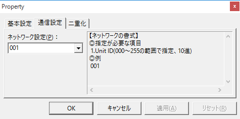
[Folder Properties]
|
Control of the IT series
When controlling (writing) the IT series (indicator light) from the host side, turn off mode switch number 8 on the main unit.
When it is ON, it becomes a contact input and cannot be controlled from the host.
If you write to the input status when it is ON, a communication error (error code "0x02") will occur.
![]()
Device (wireless router) settings
Configure the "WL40EW2". The settings are done via a web browser.
1.Enter the IP address of this machine into a web browser to display the login screen.
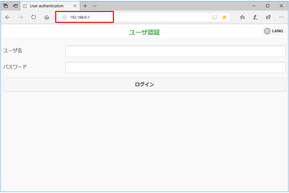
|
The factory default IP address for the WL40EW2 is "192.168.0.1". Use this IP address when connecting for the first time. If you have changed the IP address, connect using that IP address. |
2.Enter your username and password and click "Login"
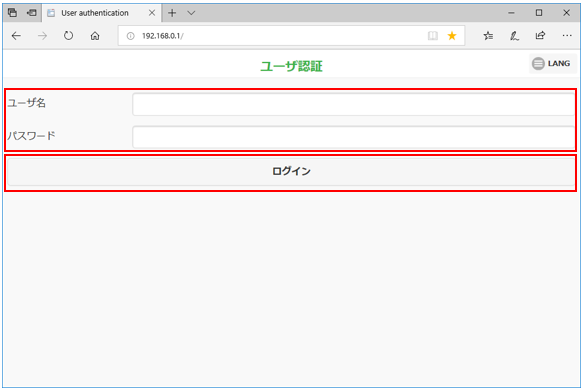
|
The factory default username/password is "admin/admin". |
3.To change the IP address, click "TCP/TP Settings."
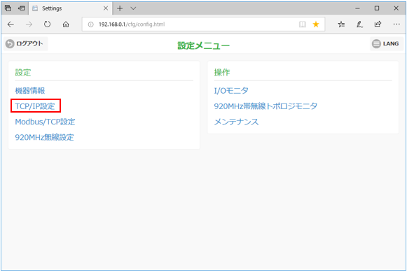
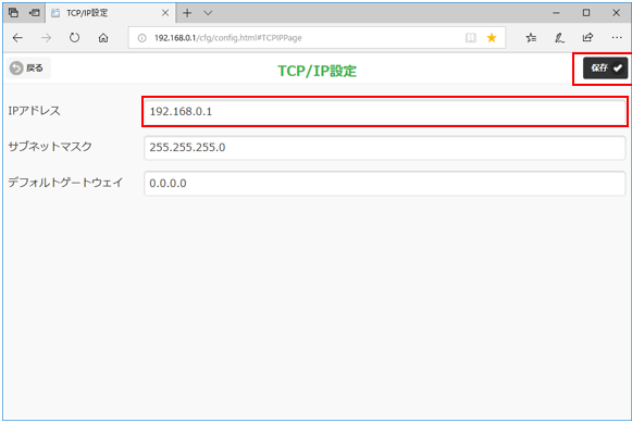
4.Specify an IP address and click "Save."
*Here, use the default IP address "192.168.0.1".
5.To change the port number for connecting to Modbus/TCP, click "Modbus/TCP Settings."
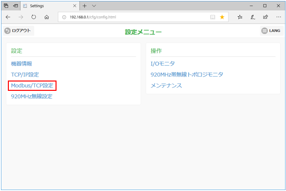
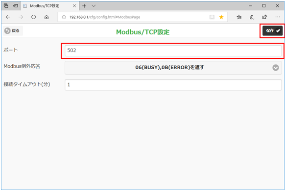
6.Specify a port number and click the Save button.
*Here, use the default port number "502".
7.From "920MHz Wireless Settings", set up the link with the signal tower
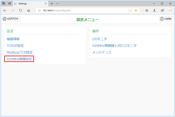
8.Configure the following settings and click the Save button.
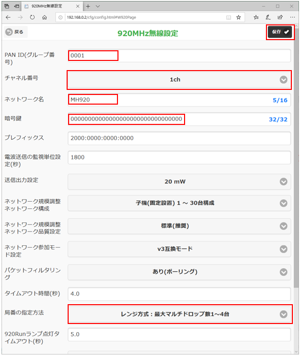
setting |
Setting contents |
PAN ID |
0001 |
Channel Number |
1 |
Network Name |
MH920 |
Encryption Key |
Optional (keep the default settings here) |
How to specify the area code |
Range method: Maximum number of multi-drops: 1 to 4 |
|
PAN Please specify a value greater than or equal to 0001 for the ID. If 0000 is specified, wireless communication will be stopped and communication will be impossible. |
|
If you specify the range method as the station number specification method, station numbers (node numbers) will be assigned in the order of short addresses. If you want to freely specify the connection target, select the list method and specify the short address of the child device on the station number specification screen. For details on the specification method, please refer to the device manual. |
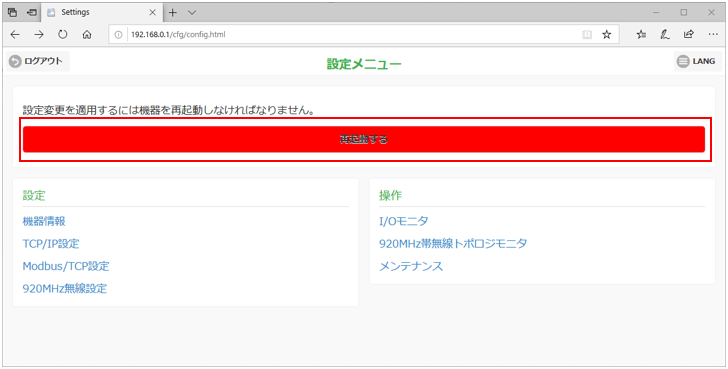
9.Reboot
Device side (indicator light) settings
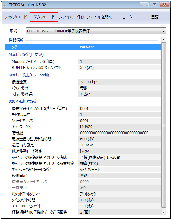
Configure "IT60SW6". The settings are done in "ITCFG".
1.Start the tool and configure the following settings:
*If you want to use the device settings, click "Upload" to load the settings onto your PC.
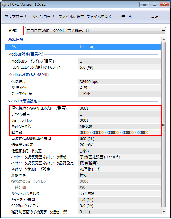
setting |
Setting contents |
format |
Select the type of device you are using |
PAN ID for priority connection |
0001 |
Channel Number |
1 |
Short Address |
0001 |
Network Name |
MH920 |
Encryption Key |
Optional (keep the default settings here) |
*Each setting should be made according to the settings of the wireless base station.
2.Click "Download" to update the settings on the device.
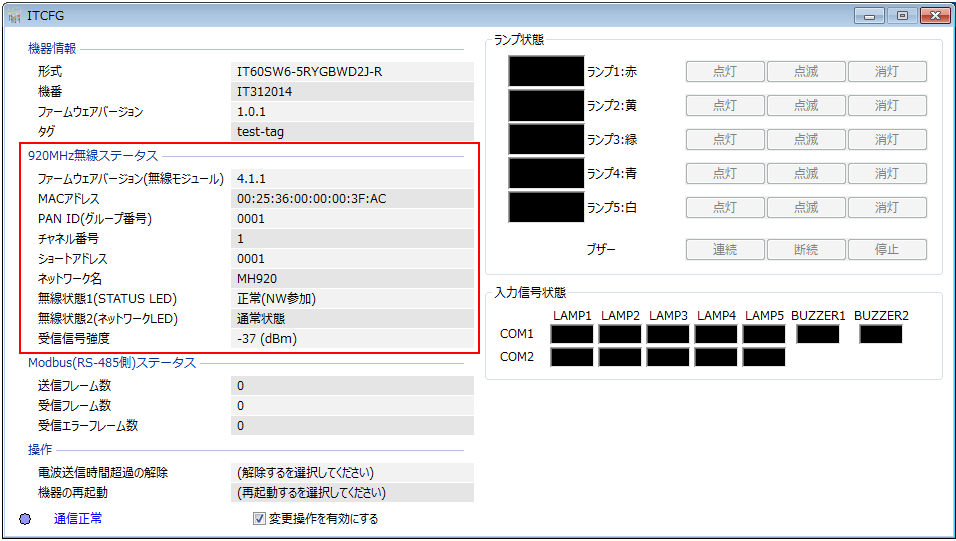
3.Click "Monitor"
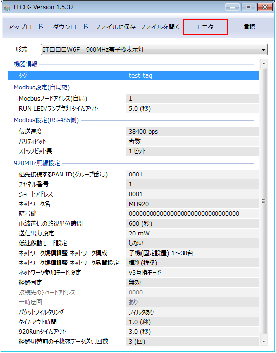
4.Check that the settings are working as configured
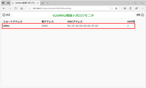
5.Open the setting screen of the wireless router and click "920MHz Wireless Topology Monitor."
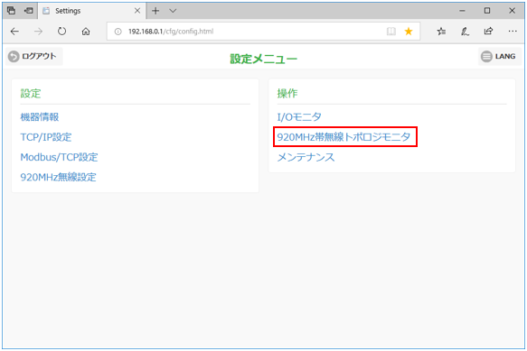
6.Check that the indicator light is part of the network
PC settings
Use the Server application to connect to the PLC for which you have set up communications.
1.Right-click "Application" - "Driver" in the tree and select Add Driver.
2.Select the following units from the displayed driver list and add them:

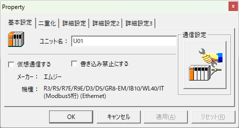
3.Open the properties of the added unit (U01) and click Communication Settings.
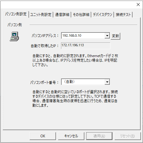
4.Configure the following in "PC Settings"
setting |
Setting contents |
Computer IP address |
192.168.0.10 |
Computer port number |
Automatic |
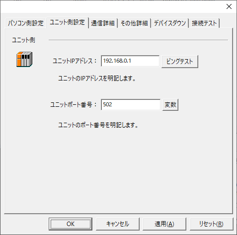
5.Set the following in "Unit side settings"
setting |
Setting contents |
Unit IP Address |
192.168.0.1 |
Unit Port Number |
502 |
6.Select "Ping Test" to check if the ping goes through normally.
If you see a message like "Ping test is success~", the test was successful.
7.Perform a connection test to check the connection
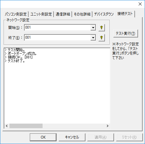
If a message such as "Connection OK" is displayed, the connection is confirmed as OK.