overview
Model used
item |
Model etc. |
device |
KW2G |
Communication Unit |
Device Attachment Port |
Configuration environment
item |
environment |
tool |
Main unit buttons |
Configuration details
item |
setting |
Setting items |
Configuration Example |
Device settings |
Set with the switch on the main unit |
protocol |
MEWTOCOL |
Area code |
1 |
||
Communication speed |
19200bps |
||
Data bits |
8bit |
||
parity |
Odd |
||
Stop bits |
1 |
||
Communication response time |
5ms |
||
PC settings |
Unit Settings |
COM port |
Communication port number to connect to |
Transmission speed |
19200bps |
||
Data bits |
8bits |
||
Stop bits |
1bits |
||
parity |
Odd |
||
Folder and communication test settings |
Destination |
01 |
* Most of the settings on the computer will be adjusted to match the settings on the unit.
About connection
To connect, use the USB 2.0 cable (mini-B type) via the USB port on the unit.
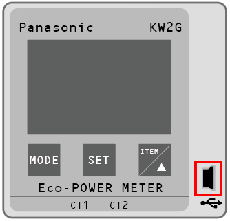
|
Please install the USB driver on the PC you will be connecting to in advance. The USB driver is included in "KW Monitor". Please download "KW Monitor" from the official Panasonic website. |
Device settings
Configure the settings for "KW2G." Settings are made using the buttons on the device.
1.Follow the steps below to display the setting screen.
①Press and hold the “MODE” button.
②When MODE1 is displayed, press the “ITEM” button twice.
③When MODE3 is displayed, press “SET”.
2.Specifying the protocol
Select the notation below and press the "SET" button.
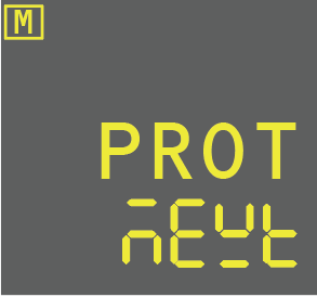
setting |
Setting contents |
PROT (protocol specification) |
MEWTOCOL |
3.Specify the area code
Select the notation below and press the "SET" button.

setting |
Setting contents |
NO (station number) |
1 |
4.Specify the communication speed
Select the notation below and press the "SET" button.
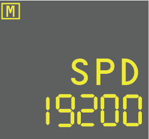
setting |
Setting contents |
SPD (Communication speed specification) |
19200 |
5.Specify the communication format (data length and parity)
Select the notation below and press the "SET" button.
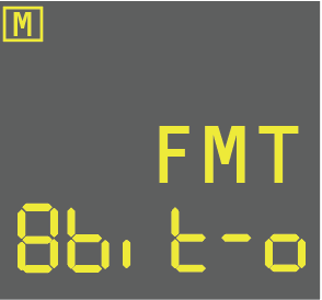
setting |
Setting contents |
FMT (data length/parity specification) |
8bit/odd |
6.Specify the stop bit
Select the notation below and press the "SET" button.

setting |
Setting contents |
STOP (specify stop bit) |
1 |
7.Specifying the communication response time
Select the notation below and press the "SET" button.

setting |
Setting contents |
RESP (communication response time specification) |
5 |
|
The time from reception to transmission for Web Data Logger Unit (DLU) and Data Logger Light (DLL) is "1.1 ms or less," so please set the communication response time of the LW2G/KW2G-H Eco-POWER METER to "5 ms or more" to allow for some leeway. |
8.Return to the initial screen and complete the setup.
PC settings
Use the Server application to connect to the device for which you have set up communications.
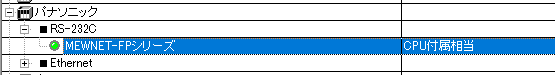
1.Right-click on "Application" - "Driver" in the tree and select Add Driver.
2.Select the following units from the displayed driver list and add them:
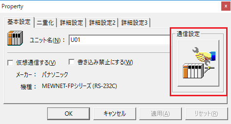
3.Open the properties of the added unit (U01) and click Communication Settings.
4.Set "Communication Settings" as follows:
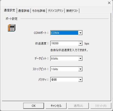
setting |
Setting contents |
COM port |
Communication port number to connect to |
Transmission speed |
19200 |
Byte Size |
8bits |
Stop bits |
1bits |
parity |
Odd |
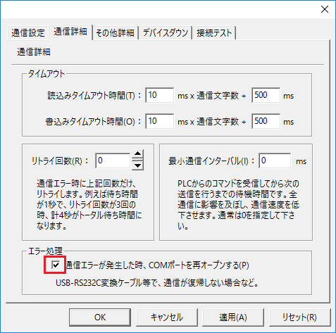
5.COM port may be locked due to communication abnormality, so check the reopen setting.
6.Perform a connection test to check the connection
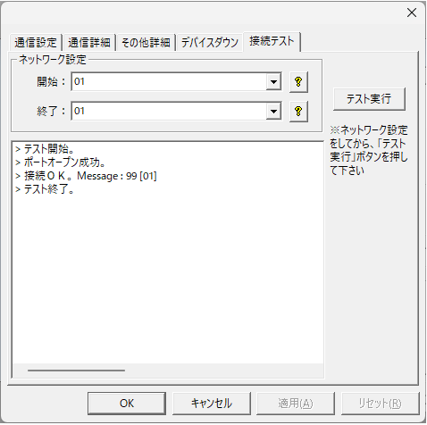
If a message such as "Connection OK" is displayed, the connection is confirmed to be OK.
Mapping and tagging
|
The contents on this page are excerpts from the KW2G manual. For details, please refer to the device manual. |
[Basic]: Basic unit [Expansion x]: Expansion unit. Registers without the [ ] mark are common items.
Data Register |
name |
unit |
Data Type |
range |
R/W |
DT00000 |
Health Status |
- |
Unsigned 16bit |
0: Normal, 1: Abnormal 0 to 7 bits (Communication error between base unit and expansion unit) 8bit (SD memory card write error) 9bit (low battery) A~Fbit (free space) |
R |
DT00020 |
[Basics] CT types |
Rated A (rms) |
Unsigned 16bit |
6 types: 5, 50, 100, 250, 400, 600 |
R/W |
DT00021 |
[Additional 1] CT type |
Rated A (rms) |
Unsigned 16bit |
|
|
DT00022 |
[Addition 2] CT type |
Rated A (rms) |
Unsigned 16bit |
|
|
DT00023 |
[Additional 3] CT type |
Rated A (rms) |
Unsigned 16bit |
|
|
DT00024 |
[Additional 4] CT type |
Rated A (rms) |
Unsigned 16bit |
|
|
DT00025 |
[Additional 5] CT type |
Rated A (rms) |
Unsigned 16bit |
|
|
DT00026 |
[Additional 6] CT type |
Rated A (rms) |
Unsigned 16bit |
|
|
DT00027 |
[Additional 7] CT type |
Rated A (rms) |
Unsigned 16bit |
|
|
DT00030 |
[Basics] Cutoff current |
0.001 |
Unsigned 16bit |
1-500 |
R/W |
DT00031 |
[Extension 1] Cut-off current |
0.001 |
Unsigned 16bit |
|
|
DT00032 |
[Extension 2] Cut-off current |
0.001 |
Unsigned 16bit |
|
|
DT00033 |
[Extension 3] Cutoff current |
0.001 |
Unsigned 16bit |
|
|
DT00034 |
[Extension 4] Cutoff current |
0.001 |
Unsigned 16bit |
|
|
DT00035 |
[Addition 5] Cutoff current |
0.001 |
Unsigned 16bit |
|
|
DT00036 |
[Extension 6] Cutoff current |
0.001 |
Unsigned 16bit |
|
|
DT00037 |
[Extension 7] Cutoff current |
0.001 |
Unsigned 16bit |
|
|
DT00040 |
[Basic] Primary current value at CT5A |
1A |
Unsigned 16bit |
1-4000 |
R/W |
DT00041 |
[Additional 1] Primary current value at CT5A |
1A |
Unsigned 16bit |
|
|
DT00042 |
[Addition 2] Primary current value at CT5A |
1A |
Unsigned 16bit |
|
|
DT00043 |
[Additional 3] Primary current value at CT5A |
1A |
Unsigned 16bit |
|
|
DT00044 |
[Additional 4] Primary current value at CT5A |
1A |
Unsigned 16bit |
|
|
DT00045 |
[Additional 5] Primary current value at CT5A |
1A |
Unsigned 16bit |
|
|
DT00046 |
[Additional 6] Primary current value at CT5A |
1A |
Unsigned 16bit |
|
|
DT00047 |
[Additional 7] Primary current value at CT5A |
1A |
Unsigned 16bit |
|
|
DT00054 |
Rate (CHG) |
0.01 |
Unsigned 16bit |
0~9999 |
R/W |
DT00055 |
CO2 Emission Factor (CO2) |
0.001kg-CO2 |
Unsigned 16bit |
0~9999 |
R/W |
DT00056 |
Simple measurement mode setting |
- |
Unsigned 16bit |
0:OFF 1:ON |
R/W |
DT00057 |
Voltage value for simple measurement |
0.1V |
Unsigned 32bit |
0~99999 |
R/W |
DT00058 |
|
|
|
|
|
DT00059 |
Power factor for simple measurement |
0.01 |
Unsigned 16bit |
0 to 100 |
R/W |
DT00061 |
[Basic] Pulse output unit |
- |
Unsigned 32bit |
1(0.001),10(0.01),100(0.1), 1000(1),10000(10),100000(100) 999 (Instantaneous power for alarm: Apply the values of DT00064,00065) 888 (Error Alert) 777 (Ratio of alarm current value: Apply the value of DT00069) 555 (Preset value for counter output: Apply the values of DT00158,00159) 333 (Standby power alarm threshold: Apply the values of DT00077,00078) 111 (General-purpose output setting: Apply the value of DT00095) |
R/W |
DT00062 |
|
|
|
|
|
DT00064 |
[Basic] Alarm value (instantaneous power) |
0.01kW |
Unsigned 32bit |
0 to 999999 |
R/W |
DT00065 |
|
|
|
|
|
DT00066 |
VT ratio |
0.01 |
Unsigned 16bit |
100 to 9999 |
R/W |
DT00068 |
Cutoff Current |
0.001 |
Unsigned 16bit |
1-500 |
R/W |
DT00069 |
[Basic] Alarm value (current value) |
0.001 |
Unsigned 16bit |
1-1000 |
R/W |
DT00070 |
Voltage Range |
- |
Unsigned 16bit |
2; 200V (fixed) |
R |
DT00071 |
Calendar timer monitor (hours and minutes) |
- |
Unsigned 16bit |
Upper byte: Hour: 00H to 23H Lower byte: Minutes: 00H to 59H |
R |
DT00072 |
Calendar timer (minutes and seconds) |
- |
Unsigned 16bit |
Upper byte: Minutes: 00H to 59H Lower byte: Seconds: 00H to 59H |
R/W |
DT00073 |
Calendar timer (date and time) |
- |
Unsigned 16bit |
Upper byte: Date: 01H to 31H Lower byte: Hour: 00H to 23H |
R/W |
DT00074 |
Calendar timer (year/month) |
- |
Unsigned 16bit |
Upper byte: Year: 00H to 99H Low-order byte: Month: 01H to 12H |
R/W |
DT00075 |
Calendar timer (day of the week) |
- |
Unsigned 16bit |
Upper byte: Day of the week: 00H to 06H |
R/W |
DT00076 |
Log cycle settings |
- |
Unsigned 16bit |
1(1),2(5),3(10),4(15),5(30),6(60) |
R/W |
DT00077 |
[Basic] Alarm value (standby current value) |
0.001 |
Unsigned 16bit |
1-1000 |
R/W |
DT00078 |
[Basic] Alarm standby time |
1min |
Unsigned 16bit |
0~9999 |
R/W |
DT00079 |
[Basic] General output judgment setting value |
- |
Unsigned 16bit |
0:OFF,1:0N |
R/W |
DT00080 |
SRAM initialization |
- |
Unsigned 16bit |
0:OFF,1:0N |
R/W |
DT00081 |
Save file format 1 |
- |
Unsigned 16bit |
0:OFF,1:0N |
R/W |
DT00082 |
Save file format 2 |
- |
Unsigned 16bit |
0:OFF,1:0N |
R/W |
DT00083 |
Save file format 3 |
- |
Unsigned 16bit |
0:OFF,1:0N |
R/W |
DT00086 Top |
[Basic] Moving average count |
- |
Unsigned 16bit |
Five types: 0, 2, 4, 8, 16 |
R/W |
DT00086 Lower |
[Addition 1] Moving average number of times |
- |
Unsigned 16bit |
|
|
DT00087Top |
[Addition 2] Moving average number of times |
- |
Unsigned 16bit |
|
|
DT00087 Lower |
[Addition 3] Moving average number of times |
- |
Unsigned 16bit |
|
|
DT00088Top |
[Addition 4] Moving average number of times |
- |
Unsigned 16bit |
|
|
DT00088 Lower |
[Addition 5] Moving average number of times |
- |
Unsigned 16bit |
|
|
DT00089Top |
[Addition 6] Moving average number of times |
- |
Unsigned 16bit |
|
|
DT00089 Lower |
[Addition 7] Moving average number of times |
- |
Unsigned 16bit |
|
|
DT00095 |
[Basic] General purpose output settings |
- |
Unsigned 16bit |
0; ON/OFF output 1: Flicker ON output 2; One shot output |
R/W |
DT00096 |
[Basic] General-purpose output ON time setting value |
0.1s |
Unsigned 16bit |
1-100 |
R/W |
DT00097 |
[Basic] General-purpose output OFF time setting value |
0.1s |
Unsigned 16bit |
1-100 |
R/W |
DT00158 |
[Basic] Preset value |
- |
Unsigned 32bit |
0 to 999999 |
R/W |
DT00159 |
|
|
|
|
|
DT00160 |
[Basic] Prescale value |
0.001 |
Unsigned 32bit |
1-100000 |
R/W |
DT00161 |
|
|
|
|
|
DT00162 |
[Basic] Maximum counting speed |
Hz |
Unsigned 16bit |
50000 or 30 |
R/W |
DT00163 |
Auto off time |
min |
Unsigned 16bit |
0 to 99 (0 is always lit) |
R/W |
DT00198 |
[Basic] Pulse output width |
ms |
Unsigned 16bit |
1-100 |
R/W |
Data Register |
name |
unit |
Data Type |
range |
R/W |
DT01000+N*100 |
CH0 preset value |
- |
Unsigned 32bit |
0 to 999999 |
R/W |
DT01000+N*100+1 |
|
|
|
|
|
DT01000+N*100+2 |
CH1 preset value |
- |
Unsigned 32bit |
0 to 999999 |
R/W |
DT01000+N*100+3 |
|
|
|
|
|
DT01000+N*100+4 |
CH0 Prescale value |
0.001 |
Unsigned 32bit |
0 to 100000 |
R/W |
DT01000+N*100+5 |
|
|
|
|
|
DT01000+N*100+6 |
CH1 Prescale value |
0.001 |
Unsigned 32bit |
0 to 100000 |
R/W |
DT01000+N*100+7 |
|
|
|
|
|
DT01000+N*100+8 |
CH0 Maximum counting speed |
Hz |
Unsigned 16bit |
30 or 50000 |
R/W |
DT01000+N*100+9 |
CH1 Maximum counting speed |
Hz |
Unsigned 16bit |
30 or 50000 |
R/W |
DT01000+N*100+10 |
CH0 Scaling Maximum Value |
- |
Signed 32bit |
-999999 to 999999 |
R/W |
DT01000+N*100+11 |
|
|
|
|
|
DT01000+N*100+12 |
CH1 Scaling Maximum Value |
- |
Signed 32bit |
-999999 to 999999 |
R/W |
DT01000+N*100+13 |
|
|
|
|
|
DT01000+N*100+14 |
CH0 Scaling minimum value |
- |
Signed 32bit |
-999999 to 999999 |
R/W |
DT01000+N*100+15 |
|
|
|
|
|
DT01000+N*100+16 |
CH1 Scaling minimum value |
- |
Signed 32bit |
-999999 to 999999 |
R/W |
DT01000+N*100+17 |
|
|
|
|
|
DT01000+N*100+18 |
CH0 Decimal point position |
- |
Unsigned 32bit |
1(1), 10(0.1), 100(0.01),1000(0.001), 10000(0.0001) |
R/W |
DT01000+N*100+19 |
|
|
|
|
|
DT01000+N*100+20 |
CH1 Decimal point position |
- |
Unsigned 32bit |
1(1), 10(0.1), 100(0.01),1000(0.001), 10000(0.0001) |
R/W |
DT01000+N*100+21 |
|
|
|
|
|
DT01000+N*100+22 |
CH0 Input Range |
- |
Unsigned 16bit |
0: 0-5V, 01: 1-5V,02: 0-20mA, 03: 4-20mA |
R/W |
DT01000+N*100+23 |
CH1 Input Range |
- |
Unsigned 16bit |
0: 0-5V, 01: 1-5V,02: 0-20mA, 03: 4-20mA |
R/W |
DT01000+N*100+24 |
CH0 Moving average count |
- |
Unsigned 16bit |
0,2,4,8,16 |
R/W |
DT01000+N*100+25 |
CH1 Moving average count |
- |
Unsigned 16bit |
0,2,4,8,16 |
R/W |
DT01000+N*100+27 |
[Expansion N] Pulse output unit |
- |
Unsigned 32bit |
1(0.001),10(0.01),100(0.1),1000(1),10000(10),100000(100) 999 (instantaneous power for alarm) 888 (Error alarm) 777 (proportion of alarm current value) 333 (Standby power alarm threshold) 111 (General purpose output setting) |
R/W |
DT01000+N*100+28 |
|
|
|
|
|
DT01000+N*100+29 |
[Expansion N] Pulse output width |
- |
Unsigned 16bit |
1-100 |
R/W |
DT01000+N*100+30 |
[Expansion N] Alarm value (instantaneous power) |
0.01kW |
Unsigned 32bit |
0 to 999999 |
R/W |
DT01000+N*100+31 |
|
|
|
|
|
DT01000+N*100+32 |
[Expansion N] Alarm value (current value) |
0.1% |
Unsigned 16bit |
1-1000 |
R/W |
DT01000+N*100+33 |
[Additional Unit N] Alarm value (standby current value) |
0.1% |
Unsigned 16bit |
1-1000 |
R/W |
DT01000+N*100+34 |
[Additional Unit N] Alarm standby time |
1min |
Unsigned 16bit |
0~9999 |
R/W |
DT01000+N*100+35 |
[Expansion N] General-purpose output judgment setting value |
- |
Unsigned 16bit |
0:OFF,1:0N |
R/W |
DT01000+N*100+36 |
[Expansion N] General-purpose output settings |
- |
Unsigned 16bit |
0; ON/OFF output 1: Flicker ON output 2; One shot output |
R/W |
DT01000+N*100+37 |
[Expansion N] General-purpose output ON time setting value |
0.1s |
Unsigned 16bit |
1-100 |
R/W |
DT01000+N*100+38 |
[Expansion N] General-purpose output OFF time setting value |
0.1s |
Unsigned 16bit |
1-100 |
R/W |
DT01000+N*100+100 |
[Expansion N] Time measurement current 1①*3 |
0.1% |
Unsigned 16bit |
0.1 to 100.0 |
R/W |
DT01000+N*100+100+1 |
[Expansion N] Time measurement current 2①*3 |
0.1% |
Unsigned 16bit |
0.1 to 100.0 |
R/W |
DT01000+N*100+100+2 |
[Expansion N] Time measurement current |
0.1% |
Unsigned 16bit |
0.1 to 100.0 |
R/W |
DT01000+N*100+100+3 |
[Expansion N] Time measurement current 2②*1*3 |
0.1% |
Unsigned 16bit |
0.1 to 100.0 |
R/W |
DT02052 |
[Basic] Pulse input terminal ① |
- |
Unsigned 16bit |
0: Pulse count 1: Maintenance |
R/W |
DT02152 |
[Additional equipment 1] Pulse input terminal ① |
- |
Unsigned 16bit |
0: Pulse count 1: Maintenance |
R/W |
DT02153 |
[Additional equipment 1] Pulse input terminal ② *1 |
- |
Unsigned 16bit |
0: Pulse count 1: Maintenance |
R/W |
N: Unit number Basic unit: N=0 Expansion unit: N=1 to 7
Measurements
Data Register |
name |
unit |
Data Type |
range |
R/W |
DT{(N+1)*100} |
Integrated active energy (①) |
0.01kWh |
Unsigned 32bit |
0-999999999 |
R/W |
DT{(N+1)*100}+1 |
|
|
|
|
|
DT{(N+1)*100}+11 |
Power factor (①) |
0.01 |
Signed 16bit |
-100~100 |
R |
DT00112 |
frequency |
0.1Hz |
Signed 16bit |
0 to 1000 |
R |
DT{(N+1)*100}+13 |
Power factor ②*1 |
0.01 |
Signed 16bit |
-100~100 |
R/W |
DT{(N+1)*100}+20 |
Effective energy (①) |
0.01kWh |
Unsigned 32bit |
0-999999999 |
R/W |
DT{(N+1)*100}+21 |
|
|
|
|
|
DT{(N+1)*100}+22 |
Integrated active power ②*1 |
0.01kWh |
Unsigned 32bit |
0-999999999 |
R |
DT{(N+1)*100}+23 |
|
|
|
|
|
DT{(N+1)*100}+24 |
Voltage (R/RS) *2 |
0.1V |
Unsigned 32bit |
0 to 999999 |
R |
DT{(N+1)*100}+25 |
|
|
|
|
|
DT{(N+1)*100}+26 |
Voltage (RT) *2 |
0.1V |
Unsigned 32bit |
0 to 999999 |
R |
DT{(N+1)*100}+27 |
|
|
|
|
|
DT{(N+1)*100}+28 |
Voltage (T/TS) *1 *2 |
0.1V |
Unsigned 32bit |
0 to 999999 |
R |
DT{(N+1)*100}+29 |
|
|
|
|
|
DT{(N+1)*100}+34 |
Current (R) *2 |
0.001A |
Unsigned 32bit |
0-60000000 |
R |
DT{(N+1)*100}+35 |
|
|
|
|
|
DT{(N+1)*100}+36 |
Current (N/S) *2 |
0.001A |
Unsigned 32bit |
0-60000000 |
R |
DT{(N+1)*100}+37 |
|
|
|
|
|
DT{(N+1)*100}+38 |
Current (T) *1 *2 |
0.001A |
Unsigned 32bit |
0-60000000 |
R |
DT{(N+1)*100}+39 |
|
|
|
|
|
DT{(N+1)*100}+40 |
Instantaneous active power (①) |
0.1W |
Signed 32bit |
-999999 to 999999 |
R |
DT{(N+1)*100}+41 |
|
|
|
|
|
DT{(N+1)*100}+42 |
Instantaneous active power ②*1 |
0.1W |
Signed 32bit |
-999999 to 999999 |
R |
DT{(N+1)*100}+43 |
|
|
|
|
|
DT{(N+1)*100}+50 |
Accumulated effective power Wh (①) |
0.001kWh |
Unsigned 32bit |
0-999999999 |
R/W |
DT{(N+1)*100}+51 |
|
|
|
|
|
DT{(N+1)*100}+52 |
Accumulated active power Wh②*1 |
0.001kWh |
Unsigned 32bit |
0-999999999 |
R/W |
DT{(N+1)*100}+53 |
|
|
|
|
|
DT00154 |
[Basic] Pulse count value |
- |
Unsigned 32bit |
0 to 999999 |
R/W |
DT00155 |
|
|
|
|
|
DT{(N+1)*100}+70 |
Voltage (R/RS) *2 |
0.1V |
Unsigned 32bit |
0 to 999999 |
R |
DT{(N+1)*100}+71 |
|
|
|
|
|
DT{(N+1)*100}+72 |
Voltage (RT) *2 |
0.1V |
Unsigned 32bit |
0 to 999999 |
R |
DT{(N+1)*100}+73 |
|
|
|
|
|
DT{(N+1)*100}+74 |
Voltage (T/TS) *1 *2 |
0.1V |
Unsigned 32bit |
0 to 999999 |
R |
DT{(N+1)*100}+75 |
|
|
|
|
|
DT{(N+1)*100}+76 |
Instantaneous active power (①) |
0.01 kW |
Signed 32bit |
-999999 to 999999 |
R |
DT{(N+1)*100}+77 |
|
|
|
|
|
DT{(N+1)*100}+78 |
Instantaneous reactive power (①) |
0.01 kvar |
Signed 32bit |
-999999 to 999999 |
R |
DT{(N+1)*100}+79 |
|
|
|
|
|
DT{(N+1)*100}+80 |
Instantaneous apparent power (①) |
0.01 kVA |
Unsigned 32bit |
0 to 999999 |
R |
DT{(N+1)*100}+81 |
|
|
|
|
|
DT{(N+1)*100}+82 |
Instantaneous active power ②*1 |
0.01 kW |
Signed 32bit |
-999999 to 999999 |
R |
DT{(N+1)*100}+83 |
|
|
|
|
|
DT{(N+1)*100}+84 |
Instantaneous reactive power ②*1 |
0.01 kvar |
Signed 32bit |
-999999 to 999999 |
R |
DT{(N+1)*100}+85 |
|
|
|
|
|
DT{(N+1)*100}+86 |
Instantaneous apparent power ② *1 |
0.01 kVA |
Unsigned 32bit |
0 to 999999 |
R |
DT{(N+1)*100}+87 |
|
|
|
|
|
DT{(N+1)*100}+88 |
CH0 Pulse input status |
- |
Unsigned 16bit |
0: OFF, 1: ON |
R |
DT{(N+1)*100}+89 |
CH1 Pulse input status |
- |
Unsigned 16bit |
0: OFF, 1: ON |
R |
DT{(N+1)*100}+90 |
CH0 Digital conversion value |
- |
Signed 32bit |
-999999 to 999999 |
R |
DT{(N+1)*100}+91 |
|
|
|
|
|
DT{(N+1)*100}+92 |
CH1 digital conversion value |
- |
Signed 32bit |
-999999 to 999999 |
R |
DT{(N+1)*100}+93 |
|
|
|
|
|
DT{(N+1)*100}+94 |
CH0 Pulse count value |
- |
Unsigned 32bit |
0 to 999999 |
R/W |
DT{(N+1)*100}+95 |
|
|
|
|
|
DT{(N+1)*100}+96 |
CH1 Pulse count value |
- |
Unsigned 32bit |
0 to 999999 |
R/W |
DT{(N+1)*100}+97 |
|
|
|
|
|
DT02000+N*100+4 |
Actual working hours①*3 |
1min |
Unsigned 32bit |
0 to 5999994 |
R |
DT02000+N*100+5 |
|
|
|
|
|
DT02000+N*100+6 |
Actual working hours①*3 |
0.1h |
Unsigned 32bit |
0 to 999999 |
R |
DT02000+N*100+7 |
|
|
|
|
|
DT02000+N*100+8 |
Actual working hours②*1*3 |
1min |
Unsigned 32bit |
0 to 5999994 |
R |
DT02000+N*100+9 |
|
|
|
|
|
DT02000+N*100+10 |
Actual working hours②*1*3 |
0.1h |
Unsigned 32bit |
0 to 999999 |
R |
DT02000+N*100+11 |
|
|
|
|
|
DT02000+N*100+12 |
Load OFF time ① * 3 |
1min |
Unsigned 32bit |
0 to 5999994 |
R |
DT02000+N*100+13 |
|
|
|
|
|
DT02000+N*100+14 |
Load OFF time ① * 3 |
0.1h |
Unsigned 32bit |
0 to 999999 |
R/W |
DT02000+N*100+15 |
|
|
|
|
|
DT02000+N*100+16 |
Load OFF Time②*1*3 |
1min |
Unsigned 32bit |
0 to 5999994 |
R |
DT02000+N*100+17 |
|
|
|
|
|
DT02000+N*100+18 |
Load OFF Time②*1*3 |
0.1h |
Unsigned 32bit |
0 to 999999 |
R/W |
DT02000+N*100+19 |
|
|
|
|
|
DT02000+N*100+20 |
Load ON Time 1①*3 |
1min |
Unsigned 32bit |
0 to 5999994 |
R |
DT02000+N*100+21 |
|
|
|
|
|
DT02000+N*100+22 |
Load ON Time 1①*3 |
0.1h |
Unsigned 32bit |
0 to 999999 |
R/W |
DT02000+N*100+23 |
|
|
|
|
|
DT02000+N*100+24 |
Load ON Time 1② 1*3 |
1min |
Unsigned 32bit |
0 to 5999994 |
R |
DT02000+N*100+25 |
|
|
|
|
|
DT02000+N*100+26 |
Load ON Time 1② 1*3 |
0.1h |
Unsigned 32bit |
0 to 999999 |
R/W |
DT02000+N*100+27 |
|
|
|
|
|
DT02000+N*100+28 |
Load ON Time 2①*3 |
1min |
Unsigned 32bit |
0 to 5999994 |
R |
DT02000+N*100+29 |
|
|
|
|
|
DT02000+N*100+30 |
Load ON Time 2①*3 |
0.1h |
Unsigned 32bit |
0 to 999999 |
R/W |
DT02000+N*100+31 |
|
|
|
|
|
DT02000+N*100+32 |
Load ON Time 2②*1*3 |
1min |
Unsigned 32bit |
0 to 5999994 |
R |
DT02000+N*100+33 |
|
|
|
|
|
DT02000+N*100+34 |
Load ON Time 2②*1*3 |
0.1h |
Unsigned 32bit |
0 to 999999 |
R/W |
DT02000+N*100+35 |
|
|
|
|
|
DT02000+N*100+36 |
Load ON Time 1 Rate ① *3 |
0.1% |
Unsigned 16bit |
0.0 to 100.0 |
R |
DT02000+N*100+37 |
Load ON Time 2 Rate ① *3 |
0.1% |
Unsigned 16bit |
0.0 to 100.0 |
R |
DT02000+N*100+38 |
Load ON time 1 Rate ②*1*3 |
0.1% |
Unsigned 16bit |
0.0 to 100.0 |
R |
DT02000+N*100+39 |
Load ON time 2 Rate ②*1*3 |
0.1% |
Unsigned 16bit |
0.0 to 100.0 |
R |
DT02000+N*100+40 |
Maintenance in progress flag ① *3 |
- |
Unsigned 16bit |
0: Disabled 1: Running |
R/W |
DT02000+N*100+41 |
Maintenance in progress flag ② *1 *3 |
- |
Unsigned 16bit |
0: Disabled 1: Running |
R/W |
DT02000+N*100+42 |
Maintenance time ① *3 |
1min |
Unsigned 32bit |
0 to 5999994 |
R |
DT02000+N*100+43 |
|
|
|
|
|
DT02000+N*100+44 |
Maintenance time ① *3 |
0.1h |
Unsigned 32bit |
0 to 999999 |
R/W |
DT02000+N*100+45 |
|
|
|
|
|
DT02000+N*100+46 |
Maintenance time ② * 1 * 3 |
1min |
Unsigned 32bit |
0 to 5999994 |
R |
DT02000+N*100+47 |
|
|
|
|
|
DT02000+N*100+48 |
Maintenance time ② * 1 * 3 |
0.1h |
Unsigned 32bit |
0 to 999999 |
R/W |
DT02000+N*100+49 |
|
|
|
|
|
DT02000+N*100+50 |
Hour meter measurement status ① *3 |
- |
Unsigned 16bit |
0: Load OFF hours 1: Load ON Time 1 2: Load ON Time 2 3. Maintenance time |
R |
DT02000+N*100+51 |
Hour meter measurement status ② *1 *3 |
- |
Unsigned 16bit |
0: Load OFF hours 1: Load ON Time 1 2: Load ON Time 2 3. Maintenance time |
R |
N: Unit number Basic unit: N=0 Expansion unit: N=1 to 7
*1 contains the data for the second circuit in the case of a single-phase, two-wire system.
*2 Data is entered according to the set phase and wire system as shown in the table below.
Current |
Wire type |
1.R-A / R-A |
N-A / S-A |
2.R-A / T-A |
|---|---|---|---|---|
|
Single-phase two-wire system |
DT00134 - 00135 |
- |
DT00138 - 00139 |
|
Single-phase three-wire system |
|
DT00136 - 00137 |
|
|
Three-phase, three-wire system |
|
|
|
·Voltage |
Wire type |
1.R-V / R-V / RS-V |
RT-V |
2R-V / T-V / TS-V |
|---|---|---|---|---|
|
Single-phase two-wire system |
DT00124 - 00125 |
- |
DT00128-00129 |
|
Single-phase three-wire system |
DT00170 - 00171 |
DT00126 - 00127 |
DT00174 - 00175 |
|
Three-phase, three-wire system |
|
DT00172 - 00173 |
|
*3 is up to expansion unit 1 (N=0, 1).
Set tags according to the items you want to retrieve as follows:
example)
■ To obtain the "Voltage (R/RS)" (measured value) of the basic unit
The mapping is as follows:
Data Register |
name |
Data Type |
DT{(N+1)*100}+24 |
Voltage (R/RS) *2 |
Unsigned 32bit |
DT{(N+1)*100}+25 |
For the basic unit, N = 0, so the target address is "DT{(0+1)*100}+24 = DT00124".
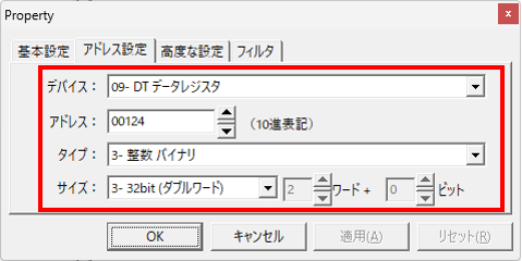
Since the data is handled as "unsigned 32 bits", the tag is specified as follows:
-Specify DT00124, select "Integer Binary" as the type and "32 Bit (Double Word)" as the size.
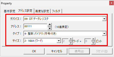
■ When obtaining the "power factor (①)" (measured value) of the basic unit
The mapping is as follows:
Data Register |
name |
Data Type |
DT{(N+1)*100}+11 |
Power factor (①) |
Signed 16bit |
The target address is "DT{(0+1)*100}+11 = DT00111".
The data type will be "signed 16-bit".
-Specify DT00111, select "Integer Binary (signed)" as the type and "16 Bit (word)" as the size.