overview
This is a connection example using the FA-M3 series Ethernet unit.
Model used
item |
Model etc. |
PLC |
FA-M3V SP71-4S |
Communication Unit |
F3LE01-0T |
Configuration environment
item |
environment |
OS |
Windows8 Professional 64Bit |
Configuration details
item |
setting |
Setting items |
Configuration Example |
PLC side settings |
Set with switch |
IP address (temporary) |
192.168.0.10 |
IP address |
192.168.0.100 |
||
Port number |
12289 (fixed) |
||
PC settings |
Unit Settings |
IP address |
192.168.0.1 |
Port number |
Automatic |
||
Communication Protocol |
UDP |
||
Folder and communication test settings |
CPU Number |
01 |
* Most of the settings on the computer will be adjusted to match the settings on the unit.
PLC side settings
Set the "F3LE01-0T". Settings are made using the side switch.
1.Set the switch as follows:

switch |
explanation |
Setting contents (hexadecimal) |
Condition SW1 |
Data Format ※Settings on the right are "Binary" |
ON |
Condition SW2 |
Write Protect * Set the setting on the right to "No." |
OFF |
Condition SW3 |
OFF Fixed |
OFF |
Condition SW4 |
OFF Fixed |
OFF |
Condition SW5 |
OFF Fixed |
OFF |
Condition SW6 |
OFF Fixed |
OFF |
Condition SW7 |
TCP Line processing when timeout occurs *The setting on the right is "Do not close" |
OFF |
Condition SW8 |
Driving Mode *The setting on the right is "Normal" |
OFF |
IP Address SW1 |
IP address first digit setting *Setting on the right is "192" |
C |
IP Address SW2 |
0 |
|
IP Address SW3 |
IP address first 2 digit setting *Setting on the right is "168" |
A |
IP Address SW4 |
8 |
|
IP Address SW5 |
IP address last 2 digit setting *Set to "0" on the right |
0 |
IP Address SW6 |
0 |
|
IP Address SW7 |
IP address last digit setting *Set the right side to "100" |
6 |
IP Address SW8 |
4 |
|
The IP address is set using 16 rotary switches. Each digit of the IP address is expressed as a hexadecimal number.
|
|
For details on the switch settings, etc., please refer to Yokogawa Electric's "Ethernet Interface Module Instruction Manual."
|
PC settings
Use the Server application to connect to the PLC for which you have set up communications.
1.Right-click "Application" - "Driver" in the tree and select Add Driver.
2.Select the following units from the displayed driver list and add them:
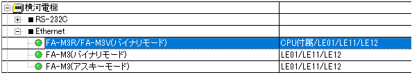
*If you are communicating in ASCII mode, please select the appropriate unit.
3.Open the properties of the added unit (U01) and click Communication Settings.

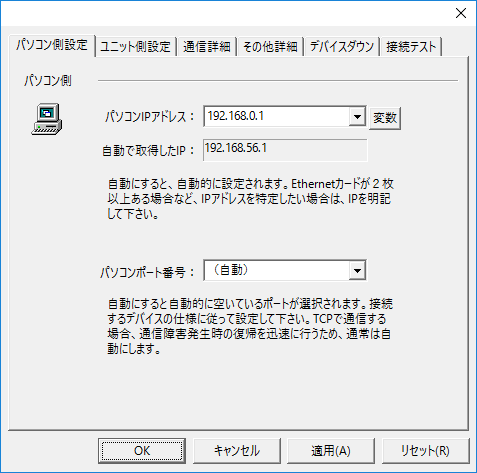
4.Configure the following in "PC Settings"
setting |
Setting contents |
Computer IP address |
192.168.0.1 |
Computer port number |
Automatic |
5.Set the following in "Unit side settings"

setting |
Setting contents |
Unit IP Address |
192.168.0.100 |
Unit Port Number |
12289 |
6.Select "Ping Test" to check if the ping goes through normally.
If you see a message such as "Ping test is success~", the test was successful.
7.Select the protocol in "Communication Details"

setting |
Setting contents |
protocol |
UDP/IP (recommended) |
8.Perform a connection test to check the connection

If a message such as "Connection OK" is displayed, the connection is confirmed to be OK.