overview
This is a connection example using the built-in Ethernet port attached to the CPU of the FA-M3 series.
Model used
item |
Model etc. |
PLC |
FA-M3V SP71-4S |
Communication Unit |
CPU Attached Port |
Configuration environment
item |
environment |
OS |
Windows7 Professional 64Bit |
tool |
WideFireld3 R4.03 |
Configuration details
item |
setting |
Setting items |
Configuration Example |
PLC side settings |
Set with tools |
IP address |
192.168.0.100 |
Port number |
12289 (fixed) |
||
PC settings |
Unit Settings |
IP address |
192.168.0.10 |
Port number |
Automatic |
||
Communication Protocol |
UDP/IP |
||
Folder and communication test settings |
CPU Number |
01 |
* Most of the settings on the computer will be adjusted to match the settings on the unit.
PLC side settings
Set up "SP76-7S". Settings are done in WideField3.
1.Launch WideField3
2.Open the menu "Online" - "Connection" and confirm that you can communicate with PLC.
3.Open "CPU Properties" in the tree
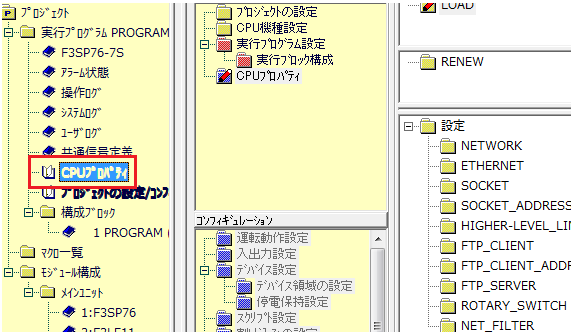
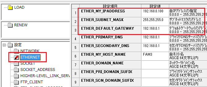
4.Open "ETHERNET" in the settings and set the following:
setting |
Setting contents |
ETHERNET_MY_IPADDRESS |
192.168.0.100 |
ETHERNET_SUBNET_MASK |
255.255.255.0 (set the default gateway to be used) |
ETHERNET_DEFAULT_GATEWAY |
192.168.0.200 (Set the IP address of the router you are using) |
*Please set other settings according to your environment.
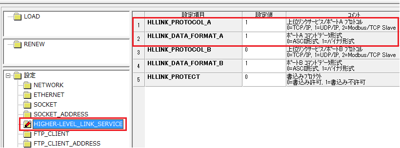
5.Open "HIGHER-LEVEL_LINK_SERVICE" in the settings and set the following:
setting |
Setting contents |
HLLINK_PROTOCOL_A |
1 (specify 0 for TCP/IP) |
HLLINK_DATA_FORMAT_A |
1 |
6.Click the "OK" button to save the settings.
7.Select "Online" - "Download [PC → CPU]" - "CPU Properties" from the menu and write the settings to PLC.
8.Reset PLC by rebooting it, etc., to reflect the settings.
PC settings
Use the Server application to connect to the PLC for which you have set up communications.
1.Right-click "Application" - "Driver" in the tree and select Add Driver.
2.Select the following units from the displayed driver list and add them:
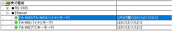
*If you are communicating in ASCII mode, please select the appropriate unit.
3.Open the properties of the added unit (U01) and click Communication Settings.
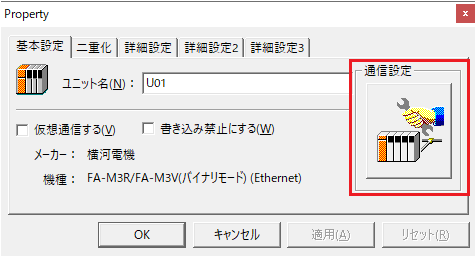
4.Configure the following in "PC Settings"
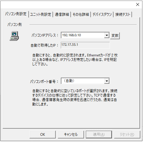
setting |
Setting contents |
Computer IP address |
192.168.0.10 |
Computer port number |
Automatic |
5.Set the following in "Unit side settings"
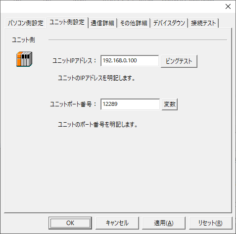
setting |
Setting contents |
Unit IP Address |
192.168.0.100 |
Unit Port Number |
12289 |
6.Select "Ping Test" to check if the ping goes through normally.
If you see a message such as "Ping test is success~", the test was successful.
7.Select the protocol in "Communication Details"
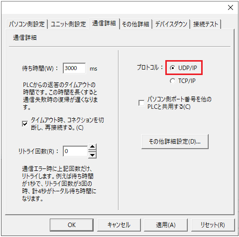
setting |
Setting contents |
protocol |
UDP/IP (recommended) |
8.Perform a connection test to check the connection
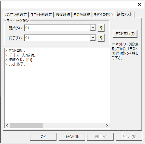
If a message such as "Connection OK" is displayed, the connection is confirmed to be OK.