overview
This is an example of a connection for the FA-M3 series "Virtual-M3".
Model used
item |
Model etc. |
PLC |
Virtual-M3 1.02 |
Communication Unit |
SP76-7S |
Configuration environment
item |
environment |
OS |
Windows7 Professional 64Bit |
tool |
WideFireld3 R4.03 |
Configuration details
item |
setting |
Setting items |
Configuration Example |
PLC side settings |
Set in system file |
IP address |
127.0.0.1 |
Port number |
12291 |
||
Connection method |
binary |
||
PC settings |
Unit Settings |
IP address |
127.0.0.1 |
Port number |
Automatic |
||
Communication Protocol |
TCP/IP |
||
Folder and communication test settings |
CPU Number |
01 |
* Most of the settings on the computer will be adjusted to match the settings on the unit.
*Here, we are using the local IP address (127.0.0.1) because we are connecting to Virtual-M3 on the same PC.
* The port number used to connect to Virtual-M3 is fixed. For details on the setting values, please refer to "PLC side settings" below.
PLC side settings
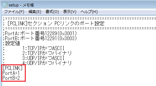
1.Check the connection method and port number of Virtual-M3
Open the system file (C:\ProgramData\yokogawa\VFAM3_Sys\setup.ini) in a text editor such as Notepad and check the settings.
In this example, the connection will be made via PortB (TCP/TP and binary, port number: 12291) with the default settings (PortA=1, PortB=2).
|
The connection method and port number for connecting to Virtual-M3 are as follows.
The port number cannot be changed.
If you want to change the communication settings, you will need to edit a system file.
System files C:\ProgramData\yokogawa\VFAM3_Sys\setup.ini
·setting Edit the PortA and PortB values of [PCLINK] according to your situation.
Note that setup.ini also contains configuration information other than the parent link. Do not change any setting information other than [PCLINK].
|

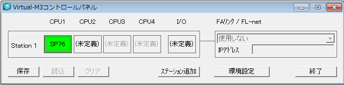
2.Right-click Station1 in Virtual-M3 and select Start.
Here, we will connect to the SP76-7S defined in CPU1 of Station1.

3.Verify that the target CPU starts normally (green light is on).
4.Select "Online" - "Connect" from the WideFireld3 menu.
5.Press Communication Settings

6.Check "Connect to Virtual-M3", specify the target Station number and CPU number, and click "OK".
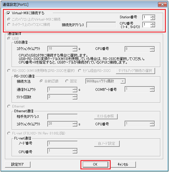
7.Click "OK" on the setting screen.

8.Confirm that WideFireld3 and Virtual-M3 are connected and that the status indicators "RDY" and "RUN" are lit green.

|
If the ladder is downloaded to the Virtual-M3 side and the program is not running, the "RUN" does not light up. In that case, download the ladder to the Virtual-M3 from the WideFireld3 menu "Online" - "Download [PC → CPU]". |
PC settings
Use the Server application to connect to the PLC for which you have set up communications.
1.Right-click "Application" - "Driver" in the tree and select Add Driver.
2.Select the following units from the displayed driver list and add them:

*If you are communicating in ASCII mode, please select the appropriate unit.
3.Open the properties of the added unit (U01) and click Communication Settings.

4.Configure the following in "PC Settings"

setting |
Setting contents |
Computer IP address |
127.0.0.1 |
Computer port number |
Automatic |
5.Set the following in "Unit side settings"

setting |
Setting contents |
Unit IP Address |
127.0.0.1 |
Unit Port Number |
12291 |
6.Select "Ping Test" to check if the ping goes through normally.
If you see a message such as "Ping test is success~", the test was successful.
7.Select the protocol in "Communication Details"

setting |
Setting contents |
protocol |
TCP/IP |
8.Perform a connection test to check the connection
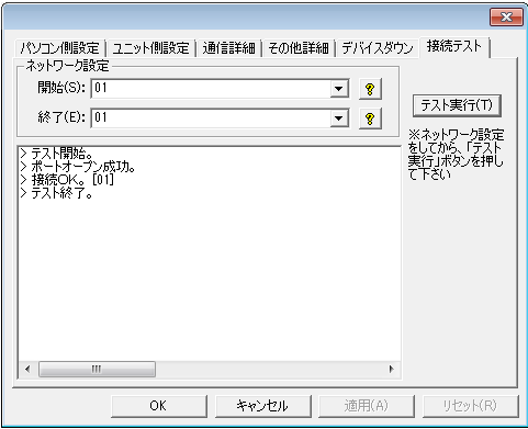
If a message such as "Connection OK" is displayed, the connection is confirmed to be OK.