FA-Server communication line
FA-Server communications can be broadly categorized into communications between FA-Server and PLC, communications between FA-Server and FA-Client, and communications for duplication processing. From here on, these communication paths will be referred to as the "PLC line," "client line," and "duplication communication line," respectively.
Communication Line |
Contents |
PLC Line
|
Communication line between FA-Server and PLC. |
Client Line
|
Communication line between FA-Server and FA-Client. |
Duplex communication line
|
This is a communication line between the main and sub FA-Server in a redundant system. It is used to check whether the main and sub are alive or not. |
Network configuration and reliability level
In a redundant system, reliability varies depending on the network configuration. There are two points to improve reliability:
▪Use two redundant communication lines
A maximum of two redundant communication lines can be set: "Redundant communication line 1" and "Redundant communication line 2." Although it is possible to operate with only one redundant communication line, we recommend that you prepare two lines to prevent the risk of the redundant communication line becoming unusable due to a failure.
▪Use multiple LAN cards
Install multiple LAN cards in the main and standby PCs and use different network paths for different purposes. By setting up the PLC line, client line, and redundant communication line to use dedicated LAN paths, reliability is improved against network failures such as LAN card or HUB failures.
Confidence Level |
Typical Configuration |
Level 1 (Not recommended) |
Configuration using only one network card. All communication lines are shared through a single communication path.
Card 1: PLC line, client line, duplex communication line 1
|
Level 2 |
Configuration using two network cards.
Card 1: Duplex communication line 1 Card 2: PLC line, client line, duplex communication line 2
*The configuration below is also acceptable, but the above configuration is better because it is desirable to have at least one line connecting both PCs with a cross cable without using a hub for the duplex communication line. However, if the communication load with PLC is large, it is better to separate the PLC line and the client line, so in such cases we recommend level 3.
Card 1: PLC line, duplex communication line 1 Card 2: Client line, duplex communication line 2
|
Level 3 |
Configuration using three network cards.
Card 1: Duplex communication line 1 ・Card 2: PLC Line Card 3: Client line, duplex communication line 2
|
* Reliability: Level 1: Low, Level 3: High
|
The duplication function switches between main and sub by periodically checking whether the other is alive. If the duplication communication line is cut, they will not be able to check each other, and the FA-Server on both the main and standby PCs will operate as main, resulting in data inconsistency. To avoid this, when using duplication, prepare at least two network cards and operate them at level 2 or higher. It is also recommended that the duplication communication line be at least one line that connects both PCs with a cross cable without using a HUB. |
Configuration example 1: When using two network cards
This is an example of a configuration using two network cards (reliability level 2).
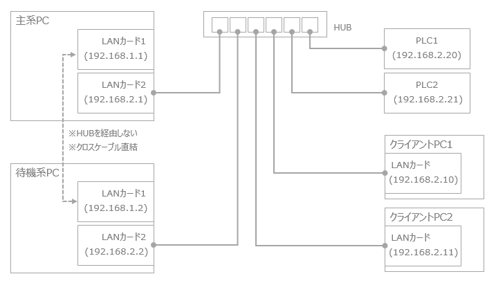
•LAN System 1: Dedicated for redundant communication line 1
•LAN System 2: For other lines (PLC lines, client lines, duplex communication line 2)
In this configuration, LAN system 1 is used exclusively for redundant communication line 1. In this way, when one system can be used exclusively for redundant communication, it is more reliable to connect the main and standby PCs directly with a cross cable rather than via a hub.
In addition, in the redundant configuration, "redundant communication line 2" uses LAN system 2 in combination with the PLC line and client line as a backup line for redundant communication.
|
When using multiple network routes, the IP address is set to a different segment address for each route. |
Configuration example 2: When using three network cards
This is an example of a configuration using three network cards (reliability level 3).
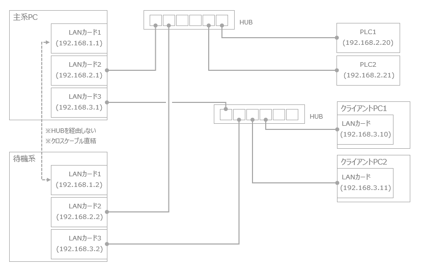
•LAN card 1: Dedicated for redundant communication line 1
•LAN Card 2: PLC Line
•LAN card 3: Used as client line and redundant communication line 2
As with Example 1, this configuration also uses LAN System 1 exclusively for redundant communication line 1 (direct connection with a cross cable). LAN System 2 is also used exclusively for the PLC line, so that other networks do not place a burden on communication with PLC. Separate devices such as HUB are also used for relay devices for each network path.