Analog output (edit box)
This section introduces an example of creating a component that uses the standard control Edit box control to write to a tag by entering a numerical value from the screen.
■ Creation procedure
The following steps assume that the following tags are registered in Panel Server.
•U01.F01.T01 - Numeric tag
1.Create a display frame with 3D frame control.
Here, we use 3D frame control as the control that will frame the input area.
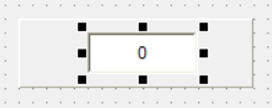
2.Paste the edit box.
Here, set the TextType property to "NUMBER".
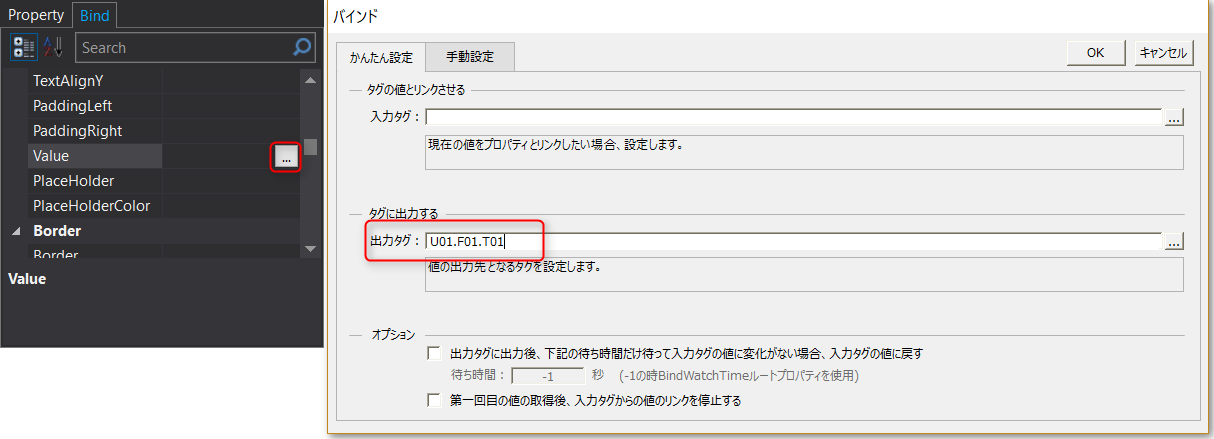
3.Bind a tag to the edit box.
Assign a tag to the binding of the Value property of the edit box. Here, we use the U01.F01.T01 tag as an example.
4.Attach a label to display the name.
Here it will display "T01 Edit".
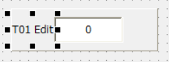
This completes the creation.
5.Operation check
When you bring
Panel Server and Panel Browser online, you will see the following:
In this example, displays with the same tag assigned are displayed side by side.
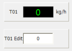
Enter a value in the edit box. Here, 77 is entered as an example.
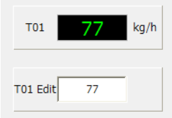
Then, the value on the upper display will also change accordingly.
This behavior means that the value edited from the edit box is written to the T01 tag of Panel Server, and the value is displayed in the display to which T01 is bound.
Analog Output (Slider)
This section provides an example of how to create a component that writes a value to a tag using a standard slider control.
■ Creation procedure
The following steps assume that the following tags are registered in Panel Server.
•U01.F01.T02 - Numeric tag
1.Create a display frame with 3D frame control.
Here we use 3D frame control as the control that will frame the input area.
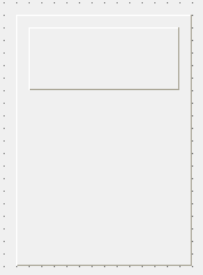
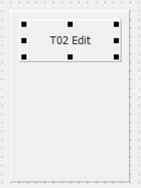
2.Attach a title label.
As an example, to bind to T02, set it to "T02 Edit".
3.Paste Vertical slider control.
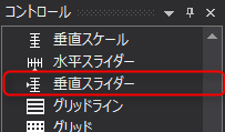
Select Vertical Slider from the Basic tab and paste it onto the screen.
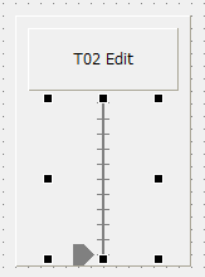
Now, change the slider’s “SliderType” property to CONTINUOUS.
By default, the slider range is set to 0 to 100, so we will use that range here.
|
By setting SliderType to CONTINUOUS, the tag value will change smoothly when you operate the slider. |

4.Bind the tag to the slider.
Bind the Value property of the slider.
Set the input tag and output tag to "U01.F01.T02".
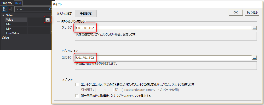
This completes the construction.
5.Operation check
When you bring Panel Server and Panel Browser online, you will see the following:
In this example, displays with the same tag assigned are displayed side by side.
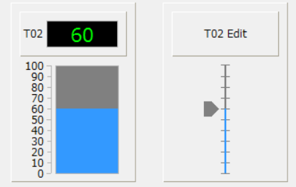
Edit the value by manipulating the slider scale with the mouse.
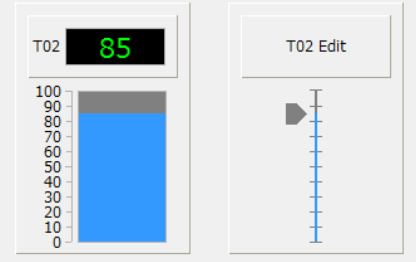
Then, the value on the display on the left will also change accordingly.
This behavior means that the value edited from the slider is written to the T02 tag in Panel Server, and the value is displayed in the indicator to which T02 is bound.
|
The maximum and minimum values (range) of the slider scale, the arrow shape and display color, and the gauge scale interval can all be changed using properties. |
|
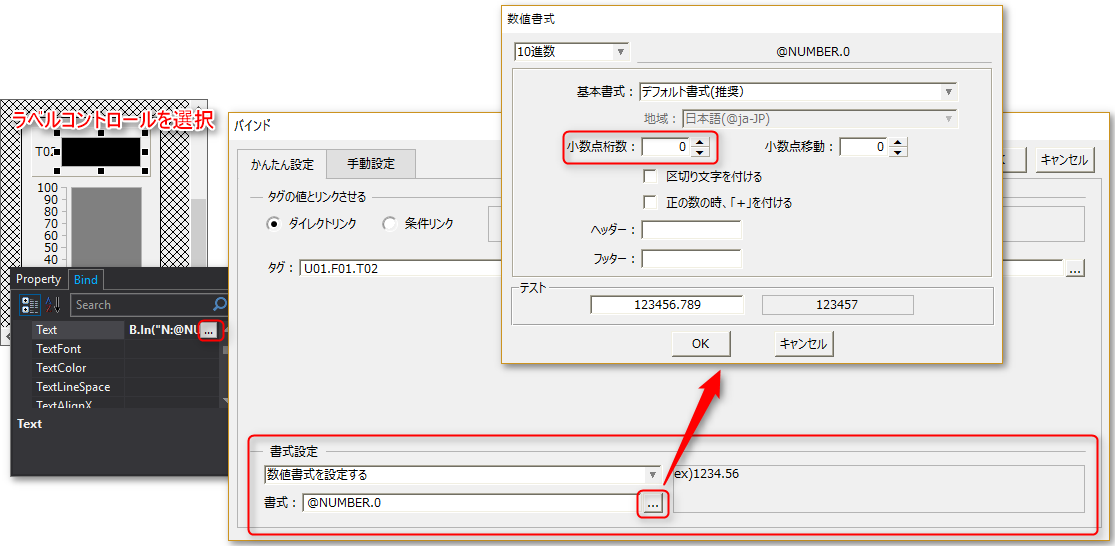
Decimal points may appear in the value of the numeric display label of the indicator when the slider is moved. If you do not want to display decimal points, specify the number format in the Binding dialog box of the indicator. |
Digital output (button operation)
This section provides an example of creating a component that uses the standard control Button control to write a ON/OFF value to a tag.
■ Creation procedure
The following steps assume that the following tags are registered in Panel Server.
•U01.F01.T51 ... bit tag
1.Create a display frame with 3D frame control.
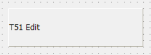
2.Paste the title Label control.
Here, as an example, to bind to the U01.F01.T51 tag, we will enter "T51 Edit".
3.Paste Button control.
To turn the T51 tag on/off, we use two Button control tags.
First, paste an ON button and change its properties.
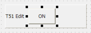
•Set the Text property to “ON”.
•Set the SwitchType property to “ON_SWITCH”.
4.Next, paste a button for OFF and change the properties. You can also create it by copying the ON button.
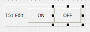
•Set the Text property to “OFF”.
•Set the SwitchType property to “OFF_SWITCH”.
|
If SwitchType is set to “ON_SWITCH”, the value of the bound tag will be turned ON by clicking the button. “OFF_SWITCH” is the opposite, and the tag value will be set to OFF. Other types of SwitchType are also available. For details, see "Button control". |
5.Bind the tag to the button.
Bind the SwitchValue property of each of the
ON and OFF buttons with the following code.
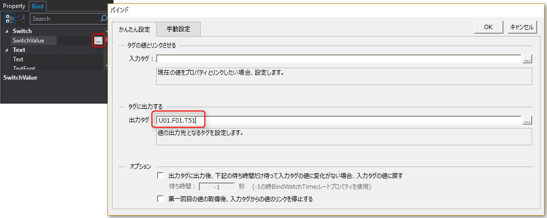
This completes the creation.
6.Operation check
When you bring
Panel Server and Panel Browser online, you will see the following:
In this example, displays with the same tag assigned are displayed side by side.
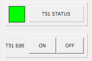
Click the ON button/OFF button and check that the color of the square on the display changes.
This behavior means that the button operation wrote a value to the T51 tag of Panel Server and the status was displayed on the display to which T51 was bound.
Digital output (toggle button operation)
This section provides an example of creating a component that uses the standard control Toggle button control to write a ON/OFF value to a tag.
■ Creation procedure
The following steps assume that the following tags are registered in Panel Server.
•U01.F01.T52 ... bit tag
1.Create a display frame with 3D frame control.
Use 3D frame control as the control that will frame the input area. Also, paste Label control for the title.
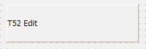
As an example, we will bind to U01.F01.T52, so we will enter “T52 Edit”.
2.Paste Toggle button control and change its properties.
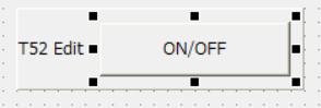
•Set the Text property to “ON/OFF”.
3.Bind the tag to Toggle button control.
Bind to the SwitchValue property of the toggle button with the following code.
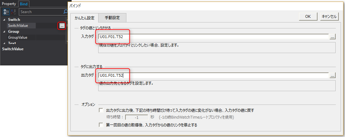
This completes the construction.
4.Operation check
When you bring
Panel Server and Panel Browser online, you will see the following:
In this example, displays with the same tag assigned are displayed side by side.
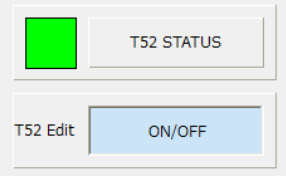
Click the button and notice that the color of the rectangle in the indicator changes.
This behavior means that the toggle button operation wrote a value to the T52 tag in Panel Server, and displayed the state of the indicator to which T52 was bound.
Digital output (image switch part)
This section introduces an example of creating a switch component using an image file, using the standard control Image switch control.
■ Creation procedure
The following steps assume that the following tags are registered in Panel Server.
•U01.F01.T53 ... bit tag
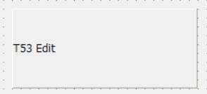
1.Create a display frame with 3D frame control.
Use 3D frame control as the control that will frame the input area, and paste Label control for the title.
2.Use Image switch control.
Paste Image switch control and change the properties.
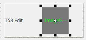
•Set the SwitchType property to "ALTERNATE_SWITCH".
•Click the Select button in the “FileOn” property to use the images from the “FA-PanelInstallation folder¥resouce¥\library\std01_ja\res” folder.
Here, select "rt_sw034.png".
•Click the Select button in the “FileOff” property to use the images from the “FA-PanelInstallation folder¥resouce¥\library\std01_ja\res” folder.
Here, select "rt_sw033.png".
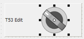
Then the image will be displayed as shown below.
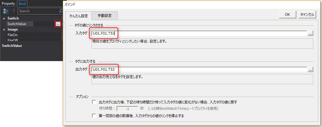
3.Bind the tag to Image switch control.
Bind a tag to the SwitchValue property of the Image switch control you just pasted. In this case, use the U01.F01.T53 tag.
4.The label shows the meaning of the switch.
Although it still functions as a switch, we'll add labels like the following to make the meaning of the switch values easier to understand.
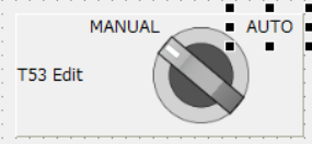
This completes the construction.
5.Operation check
When you bring Panel Server and Panel Browser online, you will see the following:
In this example, displays with the same tag assigned are displayed side by side.
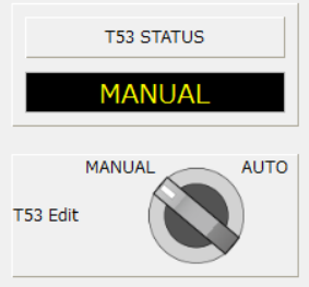
Click the switch and check that the switch image and the display unit change in tandem.
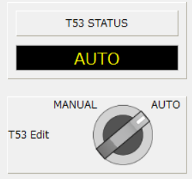
This behavior means that the image switch operation wrote a value to the T53 tag of Panel Server, and the state of the display unit to which T53 was bound changed accordingly.