overview
This is a setting example for connecting to the C series via Ethernet.
Model used
item |
Model etc. |
PLC |
C200HE |
Link Unit |
PCU01 (PC card unit) + C200HW-CE011 (bus connection unit) |
Ethernet Card |
C-NET (PC) C Contec |
Configuration environment
item |
environment |
OS |
WindowsXP Professional 32Bit |
tool |
Setup software included with the PC card unit (PCU01) |
Configuration details
item |
setting |
Setting items |
Configuration Example |
PLC side settings |
Set with tools |
IP address |
192.0.0.2 |
Port number |
9600 |
||
FINS Network Address |
1 |
||
FINS Node |
2 (the end of the IP address) |
||
IP address conversion method |
IP address table method |
||
PC settings |
Unit Settings |
IP address |
192.0.0.1 |
Port number |
9600 |
||
Folder and communication test settings |
FINS Network Address |
1 (000 is specified) |
|
FINS Node |
1 (designated 999) |
* Most of the settings on the computer will be adjusted to match the settings on the unit.
PLC side settings
EthernetBefore communicating, you must set up the Ethernet communications environment. This is done using the setup software that comes with the PC card unit (PCU01). The setup software runs on a PC.
Connect the PC card unit to the computer using a RS-232C cable and store the settings in the PC card unit. The setting procedure is described in the "Setup Software Operation" section of the "SYSMACα PC Card Unit User's Manual."
The high-level steps are as follows:
1.Connect PLC and a PC with an RS-232C (cross cable)
The cable can be connected with model number equivalent to XW2Z-XXX.
2.Copy all the files on the setup FD to a suitable directory on your hard disk.
If you want to boot directly from a
FD, please remove the write protection from the FD.
3.Launch the setup program (Setup.exe)
Run it in
MS-DOS or a Windows DOS prompt (command prompt). If you run it with the option "/j" as shown below, the display will be in Japanese.
[Example] C:\SETUP>setup /j
4.Execute "1. Enter unit IP address"
Here, set the IP address of PLC (in this case, "192.0.0.2").
5.Execute "2. Enter the unit subnet mask."
Here, set it to "255.0.0.0".
6.Execute "3. Input ODI driver"
Here, set the file name of the driver for the Ethernet card inserted in the PC card unit.
Before executing, copy the driver file for the Ethernet card to the same directory as Setup.exe. If you are using C-NET (PC) C CONTEC, it is already set up, so you do not need to perform this procedure.
7.Execute "4.HOSTS"
Please give each IP address a unique name. The name is up to you.
* The name set here will not be used in this package, but communication will not be possible without this setting.
192.0.0.1 HOST
192.0.0.2 PLC
8.Execute "5. IP-FINS Node Address Conversion Table Input"
Omron's Ethernet communication (FINS protocol) interprets a network using two numbers: the "network address" and the "node."
A network address is a number assigned to a group of multiple PLCs, including SYSNET and SYSMAC LINK, and a node is a number used to identify one PLC from that group of multiple PLCs. Therefore, node numbers are assigned to each network.
When performing 1:1 communication, the network number can be any number, but in this example we will set it to 1 (the network address will be set in the procedure below).
Here, we will assign a node number to the IP address. This will set the node number for the IP address, and you will be able to communicate with the PLC on the network using the node number during communication. This time, we will set two things as shown below.
192.0.0.1 1
192.0.0.2 2
9.Execute "6. Input of routing table"
Please execute this when setting a network address other than 1 (the default value is 1).
In this case, the network address will be set to 1, so no setting is required.
* When setting a network address, the unit number is fixed to "0".
10.Execute "8. Transfer settings to the unit"
Before that, please set the system switch on the front of the PCU-01 unit as follows, and then turn on the power. When the RUN LED lights up, data transfer will begin.
pin |
Setting contents |
Pin 1 |
OFF (Caution is required if using SYSMAC LINK or SYSNET units) |
Pin 2 |
OFF |
Pin 3 |
OFF (OFF if Ethernet card is in slot 1, ON if in slot 2) |
Pin 4 |
OFF |
Pin 5 |
ON |
Pin 6 |
OFF |
*Multiple files will be transferred, and a message will appear each time a transfer is completed. If the first file does not finish transferring after a few minutes, there may be a problem with the pin settings, so please check the settings and try again.
11.After the transfer is complete, turn pin 5 OFF and turn the power back on.
When the
RUN LED lights up, it's ready to go.
PC settings
Use the Server application to connect to the PLC for which you have set up communications.
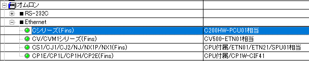
1.Right-click "Application" - "Driver" in the tree and select Add Driver.
2.Select the following units from the displayed driver list and add them:
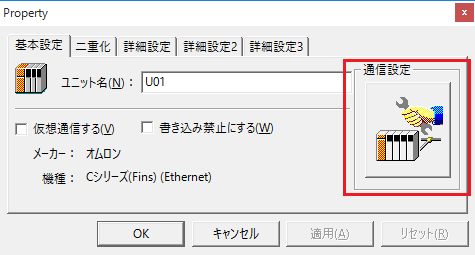
3.Open the properties of the added unit (U01) and click Communication Settings.
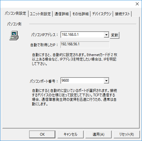
4.Set "Communication Settings" as follows:
setting |
Setting contents |
Computer IP address |
192.168.0.1 |
Computer port number |
9600 |
5.Set the following in "Unit side settings"
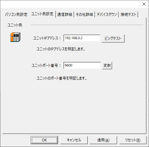
setting |
Setting contents |
Unit IP Address |
192.168.0.2 |
Unit Port Number |
9600 |
6.Select "Ping Test" to check if the ping goes through normally.
If you see a message like "Ping test is success~", the test was successful.
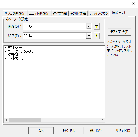
7.Perform a connection test to check the connection
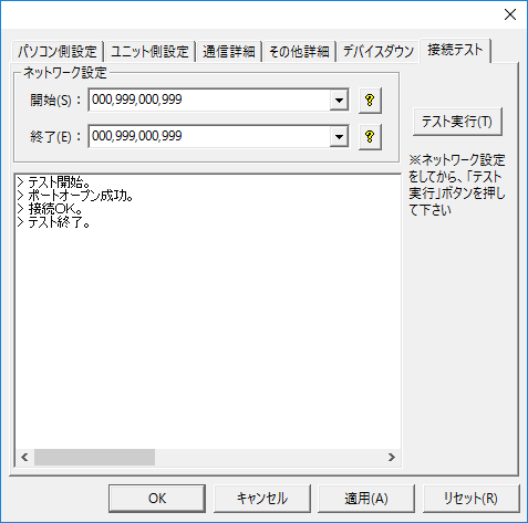
If a message such as "Connection OK" is displayed, the connection is confirmed to be OK.
|
When testing the connection and setting up the folder, do not forget to specify the node (network settings).
•Source/Destination Network Number: Please specify the network number. Specifying 000 will indicate your own network. •The source/destination node sets the node. If you specify 999, the last part of the IP address will be the node.
If you connect using the settings in this example, you can also connect by specifying "1,1,1,2".
|