About the connection example
Please see below for an example of connection settings for this driver.
Applicable models etc. |
explanation |
This is an example of connection settings with Yaskawa Electric CP-9200SH series.
|
|
This is an example of connection settings with Yaskawa Electric MP-2000 series MP2200.
|
|
Connection example [MP2000 series/MP2310]
|
This is an example of connection settings with Yaskawa Electric MP-2000 series MP2310.
|
Device List
The compatible devices are as follows (see here for how to view the device list).
device |
keyword |
Start address |
explanation |
unit |
reading |
Writing |
Input register (bit type) |
IB |
00000 |
Hexadecimal |
bit |
○ |
× |
Data register (bit type) |
MB |
000000 |
5 decimal digits + 1 hexadecimal digit |
bit |
○ |
○ |
Input Register |
IW |
0000 |
Hexadecimal |
word |
○ |
× |
Data Register |
MW |
00000 |
Decimal |
word |
○ |
● |
Techniques for high speed communication (parallel connections)
The "218IF" can have 20 simultaneous connections from a host computer, etc. Of these, 10 can process in parallel, and by configuring the following, event notification type periodic communication can be performed at high speed.
The following values are the measured communication cycle times with 5000 word devices from MW00000 to MW049999. In this example, it took 730 ms when communicating with only one connection, but when processing in parallel with 10 connections, it took about 250 ms for 5000 words.
•When communicating with one connection (approx. 730 ms/5000 words)
•When communicating in parallel with 10 connections (approximately 250 ms/5000 words)
Example of parallel connection configuration
An example configuration for parallel connections is as follows:
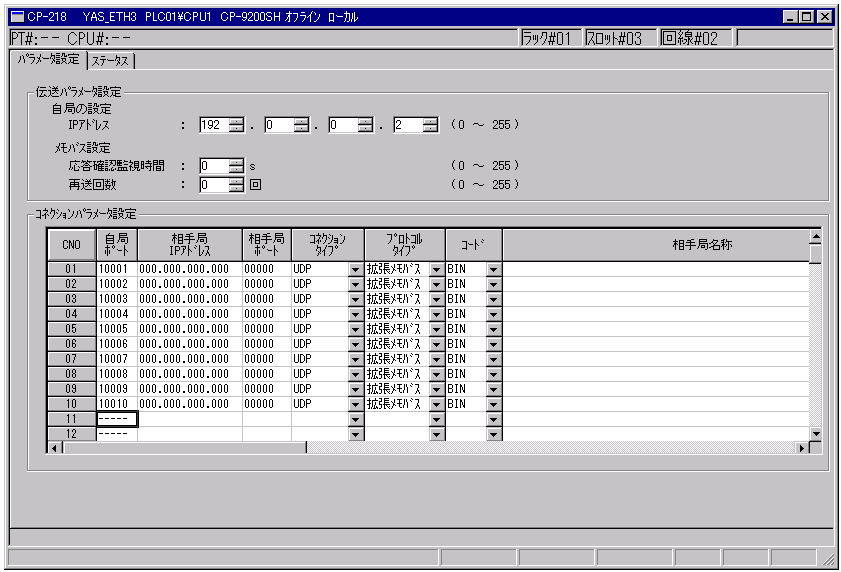
1.Set the connection parameters as follows:
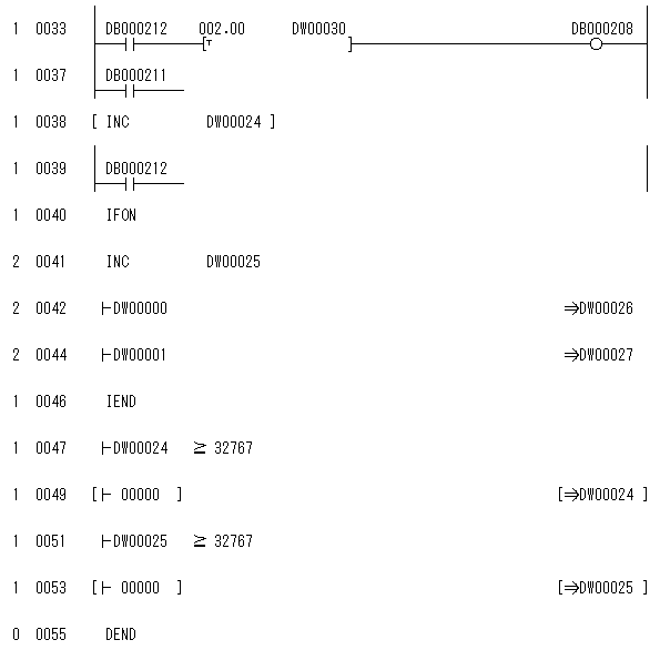
2.Write the ladder
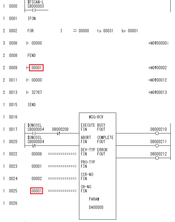
Call the MSG-RCV function for each
CNO. Below, we will explain how to prepare a drawing for each CNO.
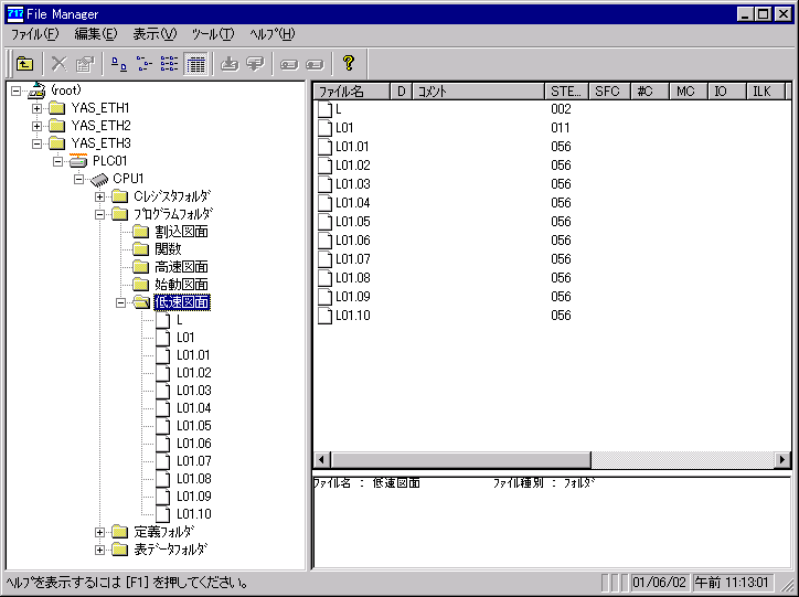
①Low speed drawing L
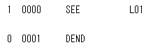
②Low speed drawing L01
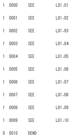
③Low speed drawings L01.01 to L01.10
The following is the drawing for L01.01. For L01.02, please change the circled part below to "0002".
Similarly, change L01.03 to L01.10 from "00003" to "00010".
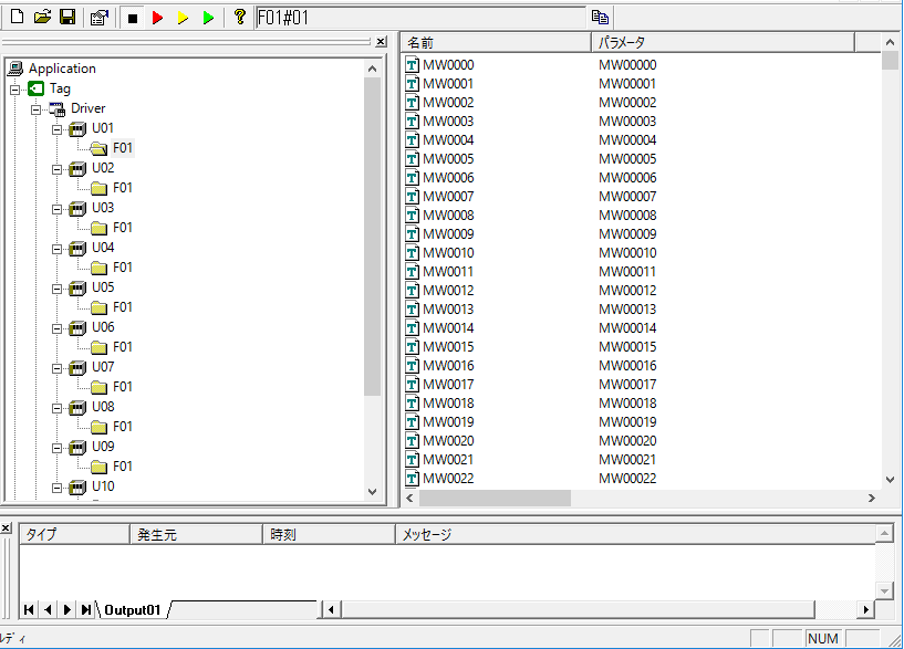
3.Configure the Server application as follows:
For example, if you want to communicate with 5000 devices using the MW register, you can communicate efficiently by doing the following.
Theoretically, communication with 10 CNOs is 10 times faster than communication with 5,000 CNOs because the data is processed in parallel.
However, the CPU processing load will be 10 times higher.
The maximum number of
IW/MW registers that can be communicated in one packet is 508 words, so one PLC will communicate 500 words at a time.
* The maximum number of IB/MB registers that can be communicated in one packet is 2000 bits (125 words).
U01.F01 MW00000~MW00499
U02.F01 MW00500~MW00999
....
U10.F01 MW04500~MW04999
Below is an example of creating a static tag.
■PLC01 Connection settings
PC port number: 10001
PLC side port number: 10001
■PLC02 Connection settings
PC port number: 10002
PLC side port number: 10002
・・・
■PLC10 Connection Settings
PC port number: 10010
PLC side port number: 10010
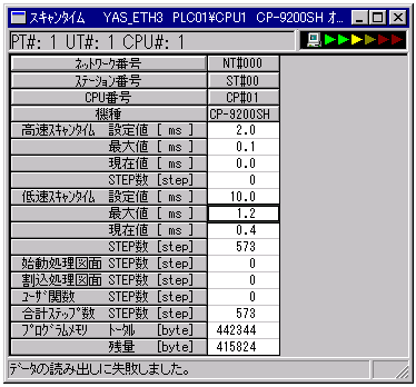
Scan time considerations
Communication time can be significantly affected by scan time. Normally, the impact is greater if the scan time is longer than the communication time per packet (approximately 60 ms). If possible, set the scan time to a maximum of approximately 20 to 30 ms. A smaller scan time will enable faster communication, but if you set it to a small value, it will have almost no impact on communication time.