overview
This is an example of setting up an Ethernet connection to CP-9200SH.
Model used
item |
Model etc. |
PLC |
CP-9200SH |
Communication Unit |
218IF |
Configuration environment
item |
environment |
OS |
WindowsXP Professional 32Bit |
tool |
Control Pack CP-717 |
Configuration details
item |
setting |
Setting items |
Configuration Example |
PLC side settings |
Set with tools |
IP address |
192.0.0.2 |
Subnet mask |
255.0.0.0 |
||
Port number |
10001 |
||
PC settings |
Unit Settings |
IP address |
192.0.0.2 |
Port number |
10001 |
||
Folder and communication test settings |
CPU Number |
01 |
* Most of the settings on the computer will be adjusted to match the settings on the unit.
PLC side settings
Set to "218IF". Settings are made using the front switch and Control Pack CP-717.
1.Set the front switch of the "218IF" as follows:
Be sure to reset the PLC after setting.
switch |
setting |
SW1 |
ACT |
SW2 |
All OFF |
For more information about the
switch, see the manufacturer's documentation.
2.Connect the "CP-9200SH" to your computer using any method.
3.Selecting a module configuration
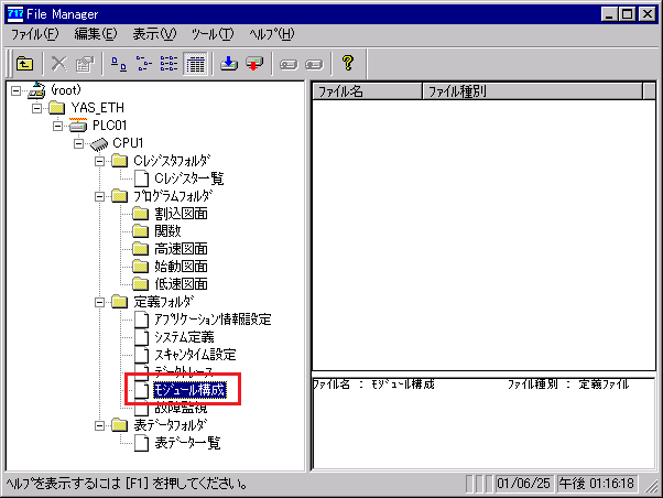
4.When you double-click "Module Configuration", the following dialog box will appear, so make the settings.
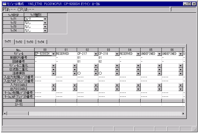
The image above shows the modules installed in the order of 9200SH/CP-217/CP-218.
5.Move the cursor to the CP-218 column and select "File" and "Open Slot" from the menu.
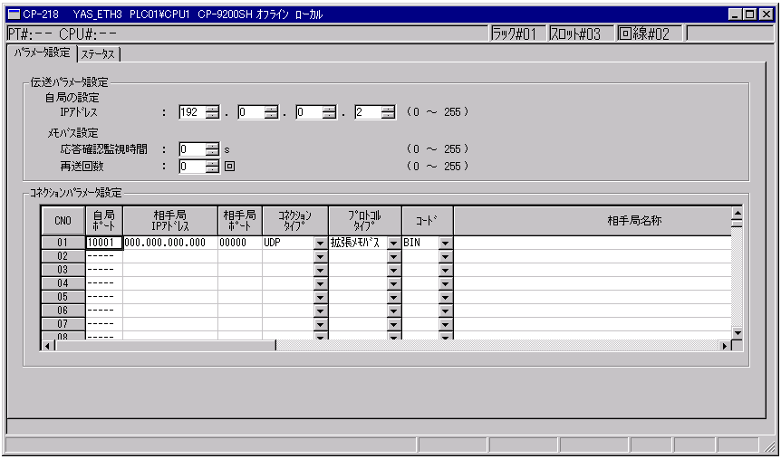
The image above does not specify the IP address of the computer or the port of the other station.
(If you want to specify the IP and port number of the computer, specify "Destination IP" and "Destination Port").
Select "Enhanced MEMOBUS" for the protocol type and "BIN" for the code.
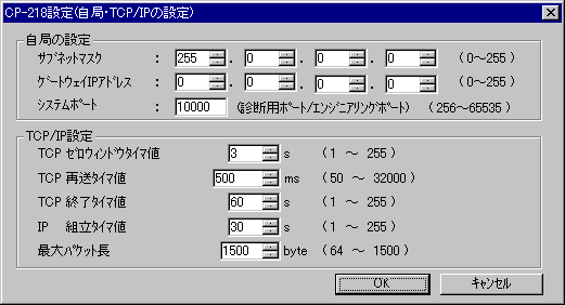
6.Open the dialog from the menu "Edit" "My Station: TCP/IP Settings" and set it as follows.
7.Write the following ladder
Draw the following ladder on the L drawing of the low-speed circuit.
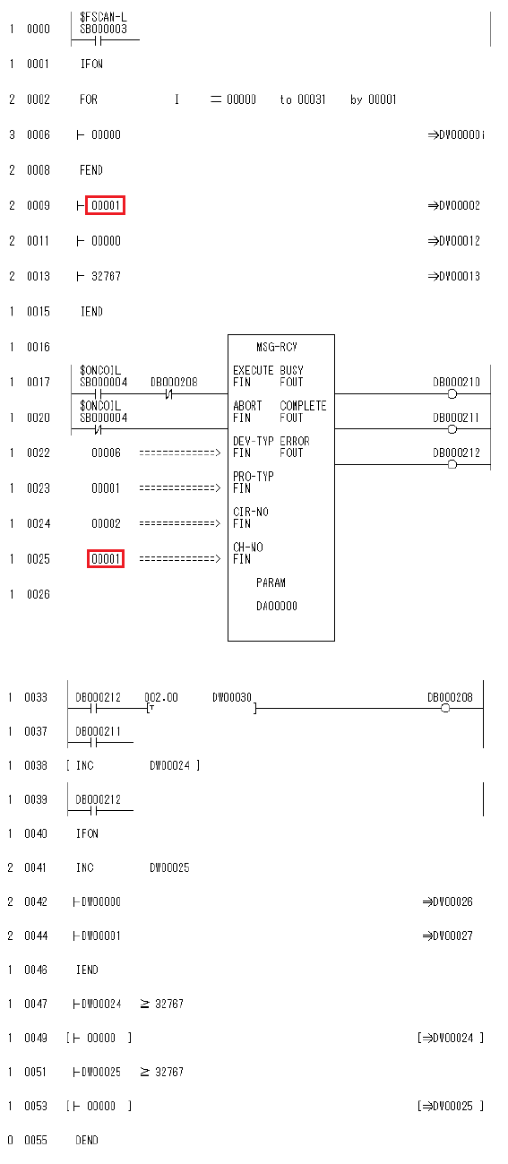
The parts marked in red (steps 9 and 25) should match the "CNO" numbers (01 to 20) in the connection parameter settings (the dialog box on the previous page for setting your own port, remote station IP address, etc.).
8.Save the settings and transfer them from the HDD to the CPU
Please restart PLC after transfer.
PC settings
Use the Server application to connect to the PLC for which you have set up communications.
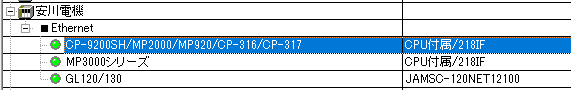
1.Right-click "Application" - "Driver" in the tree and select Add Driver.
2.Select the following units from the displayed driver list and add them:
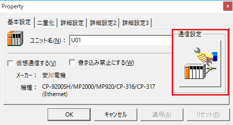
3.Open the properties of the added unit (U01) and click Communication Settings.
4.Configure the following in "PC Settings"
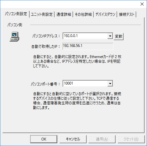
setting |
Setting contents |
Computer IP address |
192.0.0.1 |
Computer port number |
10001 |
5.Set the following in "Unit side settings"
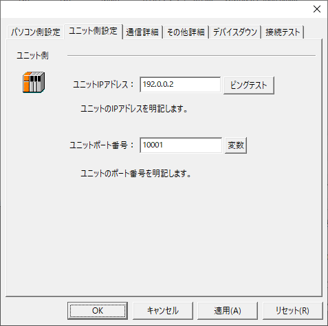
setting |
Setting contents |
Unit IP Address |
192.0.0.2 |
Unit Port Number |
10001 |
6.Select "Ping Test" to check if the ping goes through normally.
If you see a message like "Ping test is success~", the test was successful.
7.Perform a connection test to check the connection
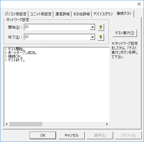
If a message such as "Connection OK" is displayed, the connection is confirmed to be OK.