overview
This is a setting example for Ethernet connection with the MP2200 of the MP2000 series.
Model used
item |
Model etc. |
PLC |
MP2200 |
Communication Unit |
218IF-02 |
Configuration environment
item |
environment |
OS |
Windows7 Professional 64Bit |
tool |
MP720 Ver7.35.0100 |
Configuration details
item |
setting |
Setting items |
Configuration Example |
PLC side settings |
Set with tools |
IP address |
192.168.1.100 |
Subnet mask |
255.255.255.0 |
||
Port number |
10002 |
||
PC settings |
Unit Settings |
IP address |
192.168.1.1 |
Port number |
10001 |
||
Folder and communication test settings |
CPU Number |
01 |
* Most of the settings on the computer will be adjusted to match the settings on the unit.
PLC side settings
1.Connect the MP2200 to your computer using any method
2.Selecting a module configuration
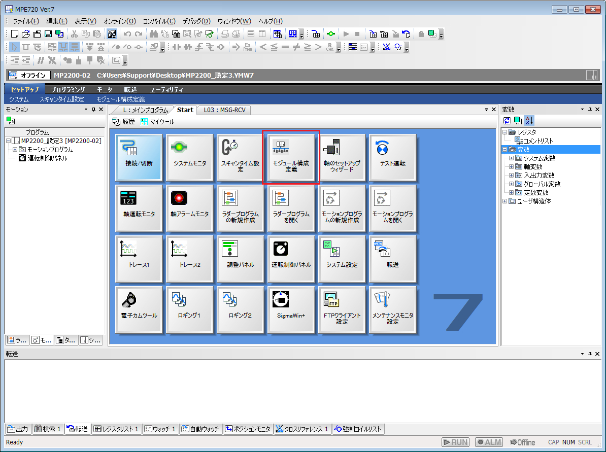
3.Set the line number of "218IF-02" from "Module Configuration"
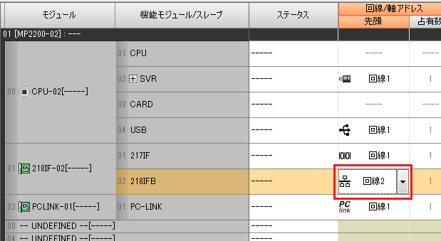
setting |
Setting contents |
Line/Axis Address |
Line 2 (please set according to your environment) |
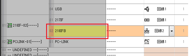
4.Double-click 218IFB to display the detailed settings screen.
5.Set up the connection such as IP
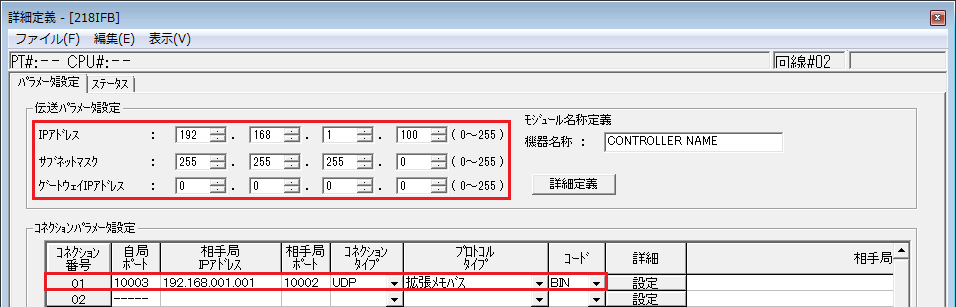
item |
setting |
Setting contents |
Transmission parameter settings |
IP address |
192.168.1.100 |
Subnet mask |
255.255.255.0 (set the IP of the default gateway to be used) |
|
Gateway IP Address |
0.0.0.0 (set the IP of the router you want to use) |
|
Connection Parameter Settings |
Local port |
10002 |
Partner station IP address |
192.168.001.001 *You must enter 001, not 1. |
|
Partner station port |
10001 |
|
Connection Type |
UDP |
|
Protocol Type |
Extended Membus |
|
code |
BIN |
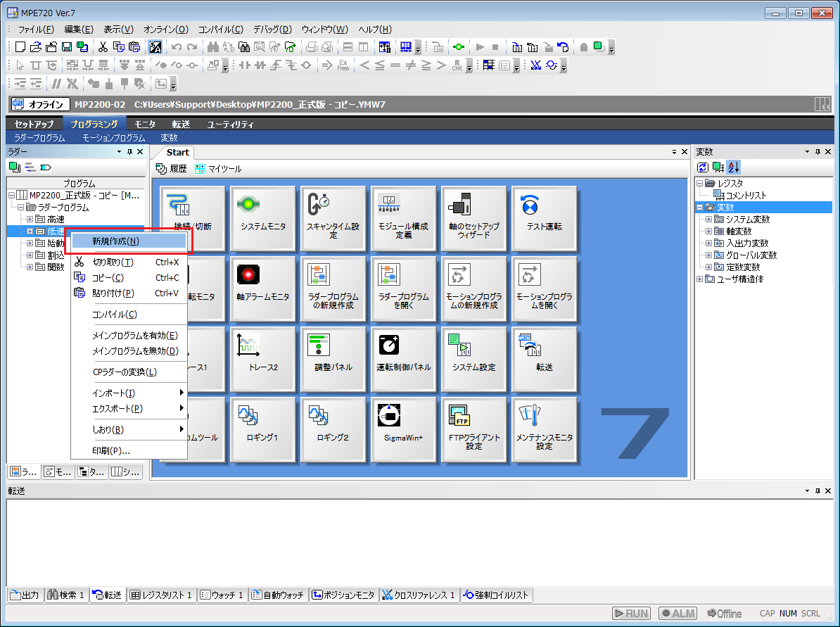
6.Adding a ladder to a slow or fast scan
This defines the slow scan.
You can add a ladder from the "Ladder Program" in the Programming tab. Right-click "Slow Speed" and select "New".
7.On the new creation screen, leave the settings as they are and click "OK"

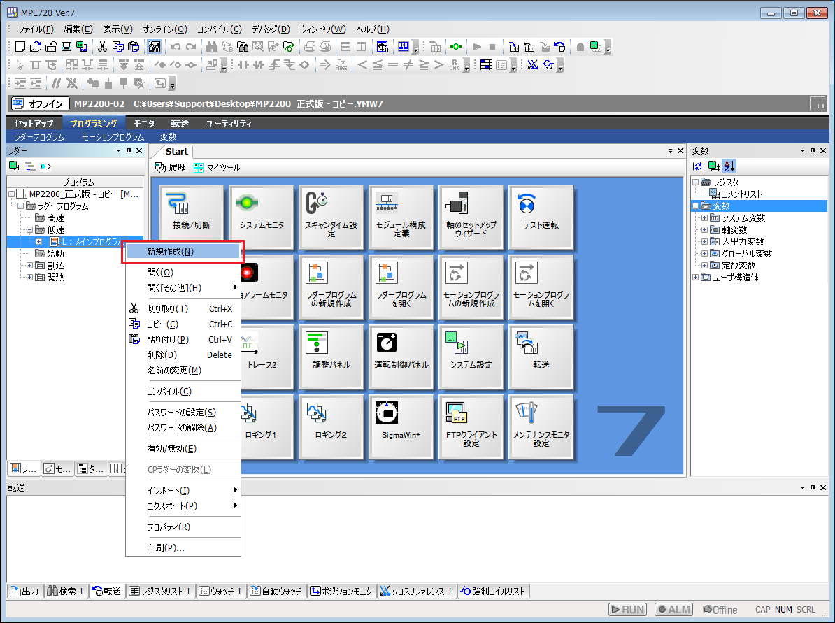
8.Add a second-level program under the added main program
Right-click Main Program and select Add New.
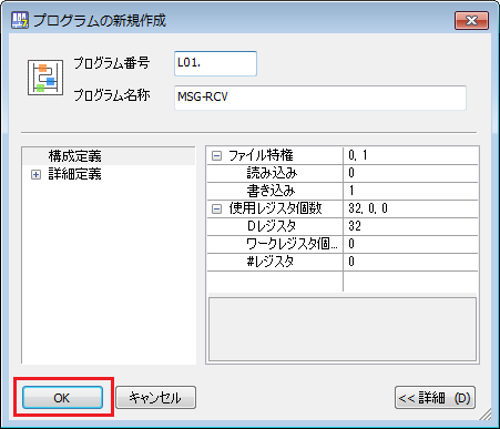
9.On the new creation screen, leave the settings as they are and click "OK"
Note that the comment "MSG-RCV" has been added here for ease of understanding.
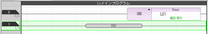
10.Main program: Write the following ladder in L
The
SEE function allows you to reference programs at the second level.
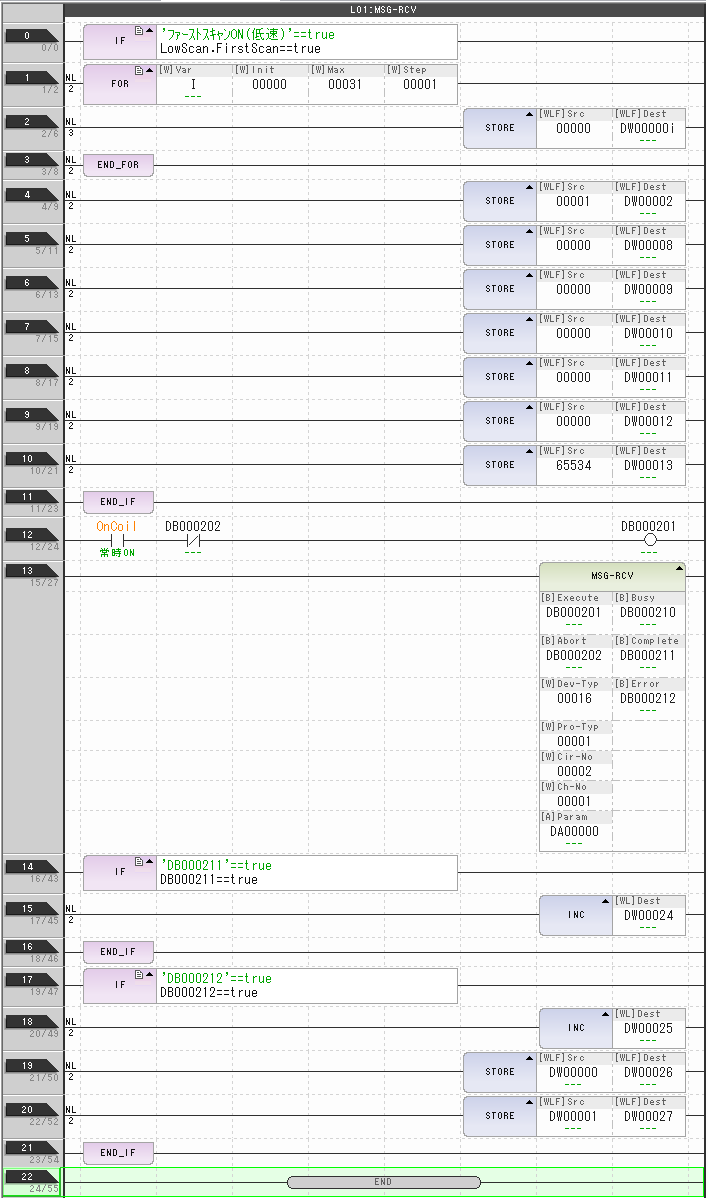
11.Second floor program: Write the following ladder in L01 (MSG-RCV)
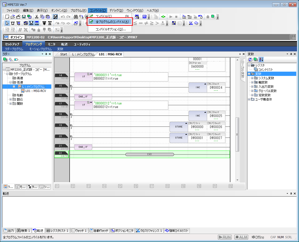
12.Compiling the program
Select the main program: L, and then choose "Compile all programs" from the Compile menu.
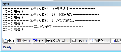
13.Check the message to see if the compilation was successful.
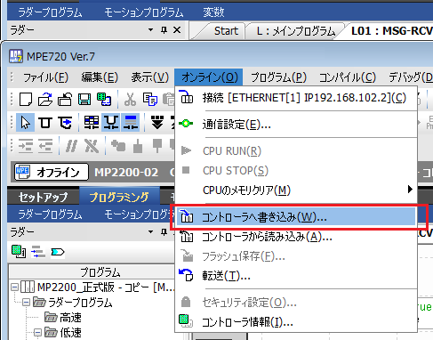
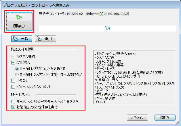
14.Select "Write to Controller" from the online menu
15.Check "System Configuration", "Programs", and "Execute flash save after transfer", then click "Start".
※Please check any other boxes as necessary.
16.Once writing is completed successfully, turn off the power to the PLC to reflect the settings.
|
The setting on the first line of the ladder MSG-RCV must be changed depending on the scan speed.
・When using low-speed scan (DWG L): Specify "SB000003==true". ・When using high-speed scan (DWG H), specify "SB000001==true".
The display format on the ladder will automatically be replaced with the internal function.
・Slow scan
-High-speed scanning
|
|
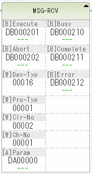
The specifications for MSG-RCV are as follows. Please set the various parameters according to your environment.
|
|
If there is a problem with the definition of MSG-RCV, an error flag will be set (DB000212 will be ON in the example setting). If you are unable to connect successfully, please check to see if any errors have occurred.
If an error occurs, check the value of the parameter storage address (DA00000 (DW00000) in the example setting). The stored value converted to hexadecimal is the error code. Error codes are listed in "Checking the processing results (PARAM00) when using the message receive function (MSV-RCV)" in Yaskawa Electric's "Machine Controller MP2000 Series Communications Module User's Manual."
Example: When the line number is set incorrectly (for example, Cir-No should be set to 2 but is set to 1) ・"-31696" is stored in DW00000. ・The error code will be "8430H" in hexadecimal notation. - When referring to "84xxH" in the manual, it says "Line number setting error: Please check the Cir-No (line number) of the message function", so review the Cir-No setting.
|
|
The ladder setting example in this section is set according to the message reception function (MSG-RCV) in the relevant module (218IF-02 in the example) in Yaskawa Electric's "Machine Controller MP2000 Series Communication Module User's Manual." For details on various settings and ladders, please refer to this manual. |
PC settings
Use the Server application to connect to the PLC for which you have set up communications.
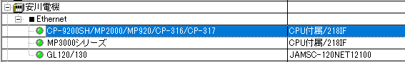
1.Right-click "Application" - "Driver" in the tree and select Add Driver.
2.Select the following units from the displayed driver list and add them:
3.Open the properties of the added unit (U01) and click Communication Settings.
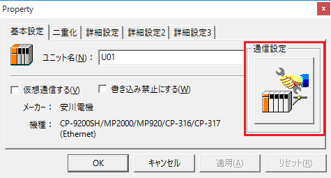
4.Configure the following in "PC Settings"
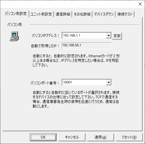
setting |
Setting contents |
Computer IP address |
192.168.1.1 |
Computer port number |
10001 |
5.Set the following in "Unit side settings"
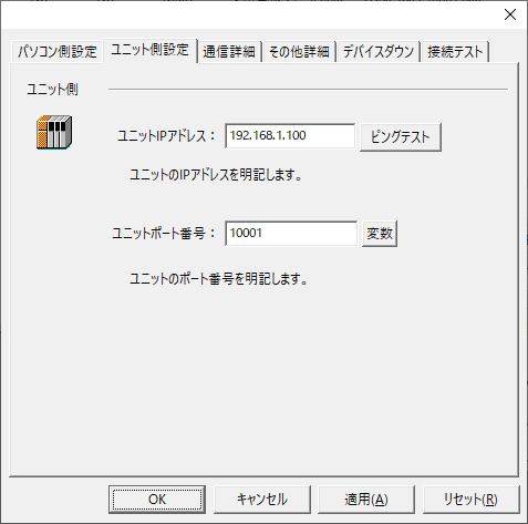
setting |
Setting contents |
Unit IP Address |
192.168.1.100 |
Unit Port Number |
10002 |
6.Select "Ping Test" to check if the ping goes through normally.
If you see a message like "Ping test is success~", the test was successful.
7.Perform a connection test to check the connection
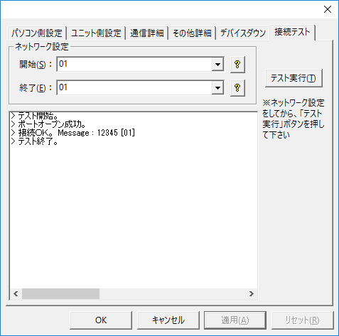
If a message such as "Connection OK" is displayed, the connection is confirmed to be OK.