overview
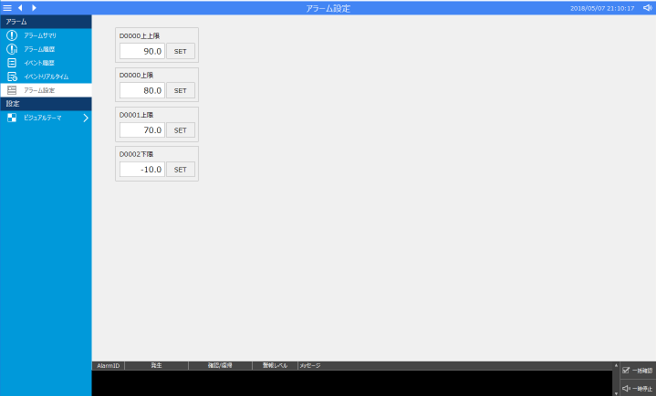
This section introduces a customization example for the standard alarm function, which allows you to change the threshold for alarm occurrence conditions from the screen.
Customization details
•Add a memory device unit to store tag values.
•Specify the tag added above as the comparison value for the alarm master occurrence condition.
•Add a form so that the values of the above tags can be changed from the screen.
(Image of alarm setting screen)
Download the sample
The creation examples shown on this page are provided with samples.
The sample can be downloaded from below.
Procedure
■Adding a memory device unit
Open the target server configuration file (server.txt) from Panel Server and add a memory device unit. This unit is used to enable the alarm thresholds set from the screen to be saved in a tag.
1.Adding a unit
|
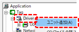
In the left tree of Panel Server, right-click Driver under Tag and select "Add Unit". |
|
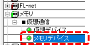
From the list of drivers, select and add Memory/Virtual Communications/Memory Device. |
|
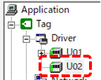
A new unit, U02, has been added. We will use this name in this customization example.
|
2.Set unit properties
Display the properties of U02 and click the Communication Settings button.
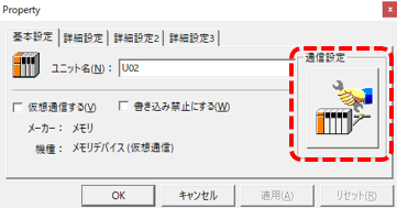
|
Select "Save values (Format 2, create a file for each unit)" from the list on the settings screen.
Also, enter the following in the value retention folder:
server_data\disktag
|
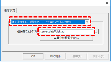
With the above settings, the tag values registered under U02 will be retained on your PC.
|
Unless there is a special reason, select "Format 2, create a file for each unit" as the value save format. |

3.Create folders and tags
Create an "F01" folder in U02 and create the following four tags under it.
Tag Name |
device |
Parameters |
Contents |
U02.F01.D0000_HIHI |
Number |
No change required (N,1) |
D0000 Upper limit threshold |
U02.F01.D0000_HI |
Number |
Ibid. |
D0000 Upper threshold |
U02.F01.D0001_HI |
Number |
Ibid. |
D0001 Upper threshold |
U02.F01.D0002_LO |
Number |
Ibid. |
D0002 Lower Threshold |
4.Write a value to a tag
Now, bring Panel Server online once and write values to the four tags added above.
Click Online (yellow arrow) at the top of the Panel Server screen.
Once Panel Server is online, select U02.F01 for Tag/Driver from the tree.
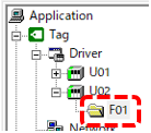
The following is displayed in the multiview. The lamps for these tags are off because they are not currently referenced.
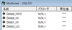
Click on any tag in the multiview to select it, and then press the "F1" key on your keyboard.
This will put you into monitoring mode as shown below.
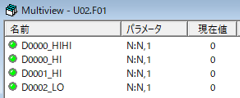
In this state, write values to individual tags (to write values, press the F5 key to display the write dialog).
For each tag, write the following values:
Tag Name |
Value to write |
U02.F01.D0000_HIHI |
90 |
U02.F01.D0000_HI |
80 |
U02.F01.D0001_HI |
70 |
U02.F01.D0002_LO |
-10 |
Once you're done writing, check to see if the value has been retained.
Please take Panel Server offline and then bring it online again.
Select U02.F01 from the tree, press the F1 key in the multiview to switch to monitoring mode, and confirm that the retention value is displayed as shown below.
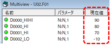
In this way, using a memory device makes it possible to store tag values on a PC.
Once you have finished checking, please take Panel Server offline.
|
In addition to storing tag values in a memory device, you can also create tags that access PLC to store values in a device on the PLC. |
■Editing the alarm master
Open the target server configuration file (server.txt) from Panel Server and add a memory device unit. This unit is used to enable the alarm thresholds set from the screen to be saved in a tag.
1.Open Alarm Master
Open "master.csv" in the following folder of the target project.
(Project folder)\server\alarm\master.csv
In the example below, it is set up to monitor analog upper and lower limit alarms (※The following is an example opened in Excel).
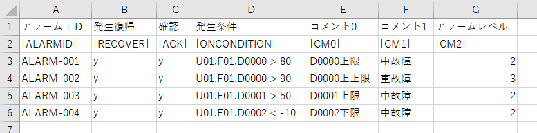
In the above settings, the threshold values for the occurrence conditions are written as fixed values.
2.Editing an Alarm Master
In the above, change the threshold value written as a fixed value so that it references the tag of the U02 unit you just added.
Below is an example configuration.
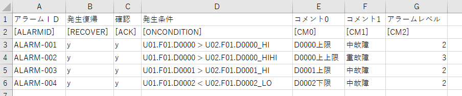
When editing the alarm master in Excel, save it in CSV format.
Below is an example edited in Notepad.
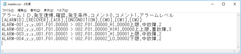
|
As shown in the above example, the alarm master trigger conditions can include multiple tags. If you want users to be able to freely change the analog upper and lower alarm thresholds after operation has started, you can achieve this by referencing the comparison value via a tag, as in this example. |
■ Creating an alarm setting screen
Next, create a setting screen for setting the alarm threshold. Here, we will explain the procedure for adding a form to a standard project that uses the standard framework.
1.Adding a Form
Please add a new form from Panel Editor.
|
As an example, we will create a form called Form01 under the User folder. |
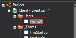
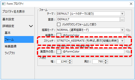
Change the form properties as follows:
|
- Set stretch (Stretch property) to "STRETCH_KEEPRATE".
- Similarly, set the off-screen color (ViewFillColor property) to "@FormColor".
|
2.Placing tag editing components
Place a component to edit the tag of the memory device in which the threshold value is stored.
As an example, we will use parts from the parts library.
From the Library tab in Panel Editor, display the numeric parts in the parts library, select the "inputnum204" part, and paste and place four of them on the form.
|
The left side is an example of the layout.
Double-click each component to display the settings dialog and configure various settings.
|
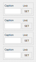
Below is an example configuration.
Target parts |
Setting items |
Setting Value |
Part 1 |
Tag settings/Input/output tags |
U02.F01.D0000_HIHI |
Display Settings > Captions |
D0000 upper limit |
|
Display settings/units |
(blank) |
|
Part 2 |
Tag settings/Input/output tags |
U02.F01.D0000_HI |
Display Settings > Captions |
D0000 limit |
|
Display settings/units |
(blank) |
|
Part 3 |
Tag settings/Input/output tags |
U02.F01.D0001_HI |
Display Settings > Captions |
D0001 Upper limit |
|
Display settings/units |
(blank) |
|
Part 4 |
Tag settings/Input/output tags |
U02.F01.D0002_LO |
Display Settings > Captions |
D0002 Lower Limit |
|
Display settings/units |
(blank) |
|
Display Settings > Minimum |
-100 |
3.Adding a screen call process to the menu
Once you have finished editing the form, create a process to call the Form01 form from a menu (or a form call button, etc.). As an example, write the following in _MenuConf to call it from the left menu of the standard framework.
(Example of setting the _MenuConf property)
[alarm] Alarm,_AlarmSummary._Main,Alarm Summary,,sys:alarmsummary_24.png,T Alarm,_AlarmHistory._Main,Alarm History,,sys:alarmhistory_24.png,T Alarm,_EventHistory._Main,Event History,,sys:eventhistory_24.png,T Alarm,_EventRealtime._Main,EventRealtime,,sys:eventrealtime_24.png,T Alarm,User.Form01,Alarm Settings,,sys:disp_details_24.png,T
[setting] Settings, [visualtheme], Visual Theme, ,sys:visualtheme_24.png ;Settings,[closeBrowser],Exit,,sys:close_24.png |
Operation check
Now let's check how it works.
Click Online (yellow arrow) at the top of the Panel Server screen.
Next, click the browser run icon (green arrow) at the top of the Panel Editor screen to call up Panel Browser.
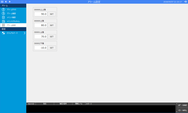
Once Panel Browser is launched, display the alarm setting screen.
|
The alarm settings screen displays the threshold settings for each alarm.
If you display the contents of the U02.F01 folder in the multi-view of Panel Server, you can confirm that the values of each tag are displayed correctly.
|
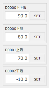
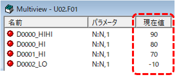
As an experiment, try editing each setting value on the screen (after changing the value, click the "SET" button to write it).
|
Please confirm that the values of each tag are updated correctly in the Panel Server multiview.
|
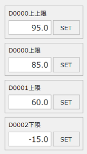
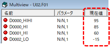
Next, try generating an alarm.
For the alarm registered to U01.F01.D0000, write a value from Panel Server that exceeds the upper limit set on the settings screen. In this example, we will write 86.
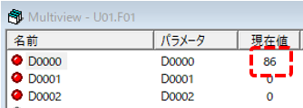
Then, a D0000 upper limit warning was displayed in the alarm summary.

Next, write a value from Panel Server to D0000 that exceeds the upper limit value set on the settings screen. In this example, we will write 96.
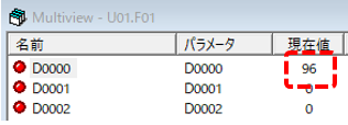
Then, a D0000 upper limit alarm was displayed in the alarm summary.
