|
The customization examples introduced on this page are old content written based on the specifications of the standard framework prior to VER6 REV11. Please interpret the following content by replacing "frmTitle" with "frmHeader" and "frmBottom" with "frmAlarm". |

overview
Remote alarm grid client control (or Remote alarm client control) has a feature called "Alarm State Monitor".
By setting an alarm state monitor, you can monitor the alarm detection status of the Alarm server to which the control is connected, and write the alarm status to a tag. This function is used when generating a representative alarm signal on the client side. The alarm state monitor is set in the AlarmStateMonitor property. For details about this property, see "Properties" in Remote alarm grid client control in the Control Reference.
Here, we will make the following customizations to the standard alarm function.
Customization details
•Configure the alarm state monitor function of the remote alarm grid and create a representative alarm signal in Browser tag.
•Add a lamp display for the representative alarm on the screen.
(Image of a representative warning light added to the title of the standard framework)

Download the sample
The creation examples shown on this page are provided with samples.
The sample can be downloaded from below.
Procedure
■ Setting the alarm state monitor function
The alarm state monitor settings should be implemented in only one control among all the alarm grids (or alarm clients) placed on the form that always exists on the client side. If the same settings are applied to multiple controls, similar monitoring processes will be executed multiple times, which may cause problems such as heavy processing load.
As an example, we will use the remote alarm grid, which is used for the alarm summary that is always displayed at the bottom of the screen in the standard framework.
|
The wizard function of the standard framework also allows you to hide the alarm summary display at the bottom of the screen. If you want to create a representative alarm signal on the client side with the alarm summary at the bottom of the screen hidden, paste Remote alarm client control into the background form (Logics.Hidden form in the standard framework) and set it. How to use the remote alarm client is described in "Sounding an alarm in your own project". |

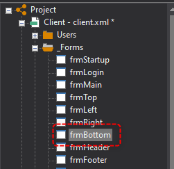
1.Select the alarm summary form at the bottom of the screen
From the Panel Editor workspace tree, select "frmBottom" under the Forms folder.
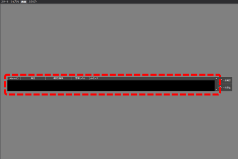
Double-click the Remote Alarm Grid located in the center of the form to display the settings dialog.
2.Set the AlarmStateMonitor property
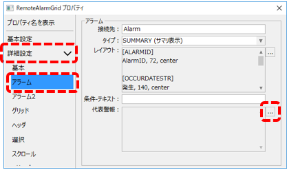
Select "Advanced Settings" and "Alarm" from the settings dialog, and click the setting button for the representative alarm (AlarmStateMonitor property).
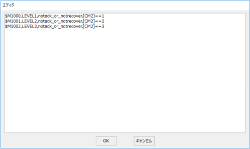
Enter the following three lines in the editor that appears and click the OK button.
(Settings)
$M1000, LEVEL1, notack_or_notrecover, [CM2]==1 $M1001, LEVEL2, notack_or_notrecover, [CM2]==2 $M1002, LEVEL3, notack_or_notrecover, [CM2]==3 |
With the above settings, if there is even one active or unacknowledged alarm for each alarm level defined in CM2, True will be written to Browser tag specified in the first parameter.
•Alarm level 1 (minor malfunction) - $M1000
•Alarm level 2 (medium failure) - $M1001
•Alarm level 3 (serious malfunction) - $M1002
■ Create a representative alarm lamp
Next, create a lamp to display the status of the representative alarm.
As an example, we will place a lamp in the title area that is always displayed at the top of the screen in the standard framework.
1.Select Forms in the title area at the top of the screen
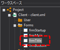
From the Panel Editor workspace tree, select "frmTitle" under the Forms folder.
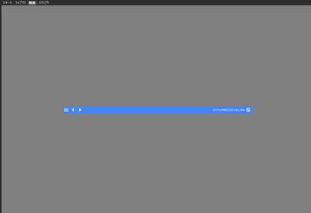
Place a lamp switch part from the parts library on the form above and add a representative alarm display.
2.Paste a part from the parts library
From the Library tab in Panel Editor, display the lamp switch parts in the parts library, select the "lampswitch123" part and paste one onto the form.

Once you have pasted it onto the form, adjust the size of the part as needed. (You can put a group of parts into edit mode by holding down the Ctrl key and double-clicking a part.)
As an example, we've adjusted the width of the Caption label to be narrower and changed the font size to 10 points.

Once you have finished adjusting the size of the part, double-click it to display the settings dialog and set it referring to the following.
subject |
Setting items |
Setting Value |
Minor fault lamp |
Tag Settings/Input Tags |
$M1000 |
|
Display Settings > Captions |
Minor malfunction |
|
Display settings/ON color |
@FAST,@AlarmColor |
|
Display settings / OFF color |
@NullColor |
|
Display Settings > Caption Color |
#FFFFFF |
Note that $M1000 specified as the input tag above is Browser tag, which was specified as the output destination for the representative signal of a minor fault in the alarm state monitor. Also, the format specified for the ON color can be simply copied and pasted from the default alarm color for parts, "@FAST,@AlarmColor". Additionally, the caption color is fixed to white (#FFFFFF).
Once you have finished setting up the minor fault lamps as described above, copy the minor fault lamps and paste them side by side.

After copying and pasting, change only the settings that are different.
subject |
Setting items |
Setting Value |
Medium fault lamp |
Tag Settings/Input Tags |
$M1001 |
|
Display Settings > Captions |
Medium failure |
|
Display settings/ON color |
(Same as minor malfunction lamp) |
|
Display settings / OFF color |
(Same as minor malfunction lamp) |
|
Display Settings > Caption Color |
(Same as minor malfunction lamp) |
Major fault lamp |
Tag Settings/Input Tags |
$M1002 |
|
Display Settings > Captions |
Serious failure |
|
Display settings/ON color |
(Same as minor malfunction lamp) |
|
Display settings / OFF color |
(Same as minor malfunction lamp) |
|
Display Settings > Caption Color |
(Same as minor malfunction lamp) |
This completes the setup process.
Operation check
Now let's check how it works.
Click Online (yellow arrow) at the top of the Panel Server screen.
Next, click the browser run icon (green arrow) at the top of the Panel Editor screen to call up Panel Browser.
Once Panel Browser is running, display the alarm summary screen.
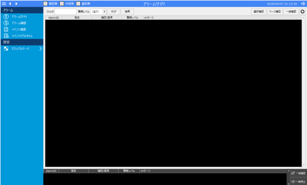
Please make sure that the representative alarm lamp you just created is placed in the title section at the top of the screen.
At present, no alarms have been issued, so all the lights are off.

If you write True to the alarm tag for a minor fault from Panel Server, the corresponding minor fault will be displayed in the alarm summary and the representative alarm lamp for the minor fault will flash.
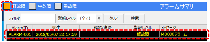
Next, write True to the alarm tags for medium failure and severe failure.
The corresponding alarm will then be displayed in the alarm summary and all representative alarm lamps will start flashing.
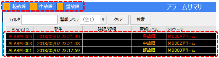
Next, from Panel Server, change the tag value for each alert back to False.
The three alarms in the alarm summary are now waiting for confirmation, but all of the main alarm lamps continue to flash.
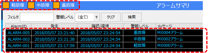
Now, select the alarms one by one from the alarm summary screen and click the "Confirm selection" button.
First, select and check the row for the serious fault alarm.

Then, the serious malfunction lamp, which had been restored and confirmed, went out.
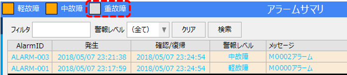
Select and check the other alarms one by one and make sure that all the main alarm lamps are turned off.

In this way, by using the Alarm State Monitor, you can easily output the status of alarms such as representative alarm signals to tags. The representative alarm output to Browser tag can be used for lamp displays on the client side, as in this example.
supplementary explanation
■ Alarm state monitor settings
The format defined for the alarm state monitor must conform to the following specifications.
Tag name, state name, monitored alarm, group condition
For example, in this example, the following is written:
$M1000, LEVEL1, notack_or_notrecover, [CM2]==1
$M1001, LEVEL2, notack_or_notrecover, [CM2]==2
$M1002, LEVEL3, notack_or_notrecover, [CM2]==3
In the first line above, if there is at least one alarm that has occurred or is unacknowledged among the alarms with a CM2 definition of 1 (i.e. minor fault alarms), True is written to the $M1000 tag.
Here, you can also specify the following for the alarm to be monitored:
notack - Writes True if there is at least one unacknowledged alarm.
notrecover - Writes True if there is at least one unrecovered alarm.
For example, you can use it according to your needs, such as when you want to see only the confirmation status or when you want to see only the return status of the actual alarm signal.
|
Be sure to specify Browser tag as the output tag for the alarm state monitor. If you specify a tag that is connected to PLC, writing to PLC may occur frequently, which may adversely affect the stable operation of the system. |