|
The customization examples introduced on this page are old content written based on the specifications of the standard framework prior to VER6 REV11. Please interpret the contents as "frmTitle" as "frmHeader". |

overview
Alarm serverActions have a feature called "status monitoring".
The Alarm server status monitoring function is a server version of the alarm state monitor available on the client side, and allows the Panel Server side to monitor the alarm detection status and write the alarm status to any tag on the server side. By using this function, it is possible to output a representative alarm signal to a tag such as a memory device. By binding and referencing the tag from the client side, it can be used to display a representative alarm lamp, etc.
Here, we will make the following customizations to the standard alarm function.
Customization details
•Add a memory device unit and prepare a tag for the representative alarm.
•Alarm serverSet the action status monitoring function and create a representative alarm signal.
•Add a lamp display for the representative alarm on the screen.
(Image of a representative warning light added to the title of the standard framework)

Download the sample
The creation examples shown on this page are provided with samples.
The sample can be downloaded from below.
Procedure
■ Add a memory device unit
Open the target server configuration file (server.txt) from Panel Server and add a memory device unit. Prepare a tag under this unit to store the representative alarm signal.
1.Adding a unit
|
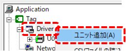
In the left tree of Panel Server, right-click Driver under Tag and select "Add Unit". |
|
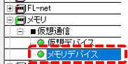
From the list of drivers, select and add Memory/Virtual Communications/Memory Device. |
|
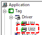
A new unit, U02, has been added. We will use this name in this customization example.
|
2.Create folders and tags
Create an "F01" folder in U02 and create the following three tags under it.
Tag Name |
device |
Parameters |
Contents |
U02.F01.ALARM_LEVEL1 |
bit |
No change required (N,1) |
Representative alarm for minor faults (unconfirmed and unrecovered) |
U02.F01.ALARM_LEVEL2 |
bit |
Ibid. |
Representative alarm for medium-sized faults (same as above) |
U02.F01.ALARM_LEVEL3 |
bit |
Ibid. |
Major fault alarm (same as above) |
■ Setting the Alarm server status monitoring function
1.Alarm serverOpen the action settings screen
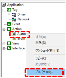
Select Alarm under Action from the tree on the left of Panel Server and right-click to open its properties.
2.Alarm serverConfigure action status monitoring
Configure status monitoring from the settings dialog.
|
Click on the "Status Monitoring" tab at the top of the screen.
|
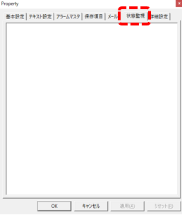
|
Enter the following in the input area in the center of the settings screen and click the OK button.
|
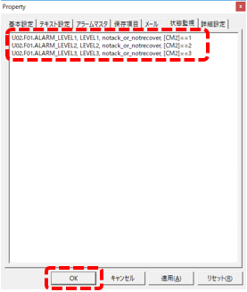
(Settings)
U02.F01.ALARM_LEVEL1, LEVEL1, notack_or_notrecover, [CM2]==1 U02.F01.ALARM_LEVEL2, LEVEL2, notack_or_notrecover, [CM2]==2 U02.F01.ALARM_LEVEL3, LEVEL3, notack_or_notrecover, [CM2]==3 |
With the above settings, if there is at least one active or unacknowledged alarm for each alarm level defined in CM2, True will be written to the tag of the memory device specified by the first parameter.
•Alarm level 1 (minor malfunction) - U02.F01.ALARM_LEVEL1
•Alarm level 2 (medium malfunction) - U02.F01.ALARM_LEVEL2
•Alarm level 3 (serious malfunction) - U02.F01.ALARM_LEVEL3
■ Create a representative alarm lamp
Next, create a lamp to display the status of the representative alarm.
This page does not explain how to create a lamp. For instructions on how to create a representative alarm lamp, please refer to the description in "Creating a Representative Alarm Signal (Client Edition)".
1.Select Forms in the title area at the top of the screen
From the Panel Editor workspace tree, select "frmTitle" under the Forms folder.
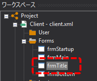
Place a lamp switch part like the one below on the frmTitle form.

Double-click to display the part's setting dialog, and set the tags as shown below.
subject |
Setting items |
Setting Value |
Minor fault lamp |
Tag Settings/Input Tags |
U02.F01.ALARM_LEVEL1 |
Medium fault lamp |
Tag Settings/Input Tags |
U02.F01.ALARM_LEVEL2 |
Major fault lamp |
Tag Settings/Input Tags |
U02.F01.ALARM_LEVEL3 |
Operation check
Now let's check how it works.
Click Online (yellow arrow) at the top of the Panel Server screen.
Next, click the browser run icon (green arrow) at the top of the Panel Editor screen to call up Panel Browser.
Once Panel Browser is running, display the alarm summary screen.
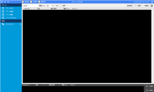
Please make sure that the representative alarm lamp you just created is placed in the title section at the top of the screen.
At present, no alarms have been issued, so all lights are off.

Write True from Panel Server to the tag being monitored for alarms, and verify that an alarm is displayed in the alarm summary and that the representative alarm lamp flashes.
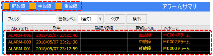
Also, make sure that all alarms are cleared and the main alarm lamp is turned off.

In this way, by using the status monitoring function of Alarm server, it becomes possible to output the status of alarms such as representative alarm signals to tags on the server side such as memory devices.
The representative alarm signal output to the tag can be used for lamp displays on the client side, and can also be used to build unique controls that are triggered by the presence or absence of a representative alarm.
supplementary explanation
■ Status monitoring settings
The format for defining status monitoring must comply with the following specifications:
Tag name, state name, monitored alarm, group condition
This format is the same as the alarm state monitor function that can be set in remote alarm grids, etc.
For example, in this example, the following is written:
U02.F01.ALARM_LEVEL1, LEVEL1, notack_or_notrecover, [CM2]==1
U02.F01.ALARM_LEVEL2, LEVEL2, notack_or_notrecover, [CM2]==2
U02.F01.ALARM_LEVEL3, LEVEL3, notack_or_notrecover, [CM2]==3
With the above settings, if there is even one alarm that has occurred or is unacknowledged among the alarms defined in CM2 as 1, 2, or 3 (i.e. minor, medium, or major failures), True will be written to the tag specified in the first parameter.
In addition, in status monitoring using Alarm server, the second parameter "status name" is simply comment information and can be omitted as follows:
U02.F01.ALARM_LEVEL1, , notack_or_notrecover, [CM2]==1
U02.F01.ALARM_LEVEL2, , notack_or_notrecover, [CM2]==2
U02.F01.ALARM_LEVEL3, , notack_or_notrecover, [CM2]==3
|
For the output tag of the Alarm server status monitoring function, please write to the tag of a unit that does not communicate with PLC, such as a virtual device or memory device. If you specify a tag that connects to PLC, writing to PLC may occur frequently, which may have a negative impact on the stable operation of the system. |

■Differences from the alarm state monitor
The Alarm server status monitoring function is similar to the alarm state monitor function of remote alarm grid, etc. The main difference between the two is whether the monitoring of alarm occurrence status is performed on the client side or the server side.
The points to consider when deciding whether to implement a function on the client side or the server side are as follows:
❑When implemented on the server side, the logic can be standardized across the entire system by defining the conditions for alarm monitoring, such as representative alarms, in one place on the Panel Server side. On the other hand, in cases where the monitoring conditions differ for each connected client, the alarm state monitor allows individual conditions to be specified on each client side.
❑There are slight differences between the two specifications, and the types of alarm field names that can be used are different. You need to choose the one that has the available fields that correspond to the requirements you want to monitor.
|
There are specification differences in the types of alarm field names that can be used in the alarm state monitor and Alarm server state monitoring. For details on the field names that can be used in state monitoring, see "About field names". |