overview
This is an example of creating a simple signal list using Grid control.
This section explains how to create a digital list screen that displays tag names, lamp indications, and comments in list format.
|
For more information about Grid control, please see "Grid control". |

|
In the example shown here, we will use a script to describe the process. For more information on scripts, please refer to "Scripts" in the Screen Creation Guide. |
Steps for creating a digital list screen
1.Prerequisites
In this example, it is assumed that the following tags are registered on the Panel Server side.
- Tag name: 15 consecutive tags from U01.F01.T51 to U01.F01.T65
- Bit type tags
2.Preparing the form for analog listing
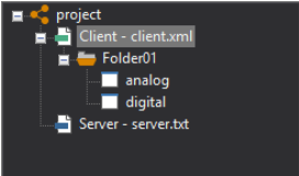
Add one form and change the form name to "digital".
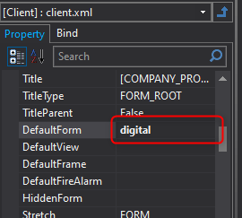
After changing the name of the form, change the DefaultForm root property of the root properties to "digital". Note that if you have multiple forms in your environment and want to use a different form as the startup form, this setting is not necessary.
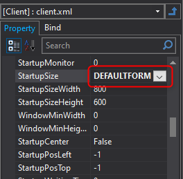
Next, for example, change the StartupSize root property to "DEFAULTFORM". Please feel free to set this according to the screen size you are using.
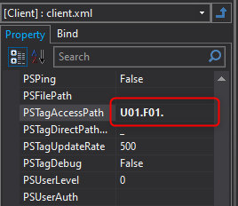
Next, we will use the access path as an example this time. Set the root PSTagAccessPath property to "U01.F01.".
|
The root PSTagAccessPath property can be used to set a tag path prefix. This prefix is called "Access Path". In the above example, "U01.F01." is set, and by doing this, tag names such as "T01" can be specified when binding or specifying tag names from scripts. However, a limitation of this function is that it is not possible to connect to tags other than those under "U01.F01.". When connecting to multiple PLCs or registering tags in separate folders, do not use the PSTagAccessPath root property. |
3.Creating a screen layout
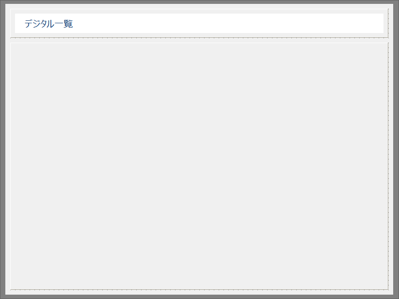
Use 3D frame control and Label control to create your own screen layout.
The following is an example.
4.Paste Grid control
Place Grid control near the center of the screen above.
From the control view, select Grid control and paste it into the form.
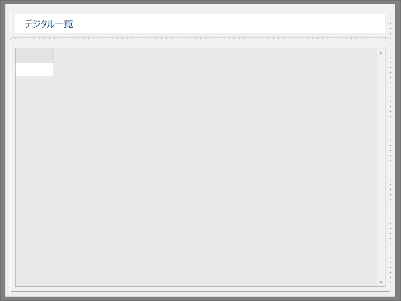
The above is the state immediately after pasting the grid.
Change the grid properties below.
・Set DefaultHeight to 30
・Set HeaderCols to 0
・Set HorizontalScroll to False
*Properties other than those mentioned above can be changed using scripts.
5.Grid initialization script
To use a grid, you must initialize the object from a script. Write the initialization script in the grid's OnInitialize event.
Please write the script in the OnInitialize event by referring to the following.
event OnInitialize() |
|
The lamp display format (lamp shape) is: this.SetCellProperty("col", "Shape", "circle", 1); Here, a "circle" ("circle") is specified, but it is also possible to specify a "square" ("square") or other shapes. The lamp display color is as follows: this.SetCellProperty("col", "OnColor", "#00FF00", 1); this.SetCellProperty("col", "OffColor", "#666666", 1); In this case, On is green and Off is gray.
|
6.Grid refresh script
Next, write a script to dynamically update the grid display. As with the analog list, write the following script in the OnTagValueChanged event of Grid control.
event OnTagValueChanged(tagname,value) |
This completes the creation of the digital listing form. Save the settings file.
|
The OnTagValueChanged event has two parameters: “tagname” and “value”. tagname is the name of the tag where the change was detected, and value is the value of that tag. In the above example, the script is written as follows: |
Operation check
Check the operation of the digital list you created. Please check while Panel Server is online.
1.Clicking the Panel Editor icon below will launch Panel Browser and open and run the client configuration file.

2.The digital list is displayed.
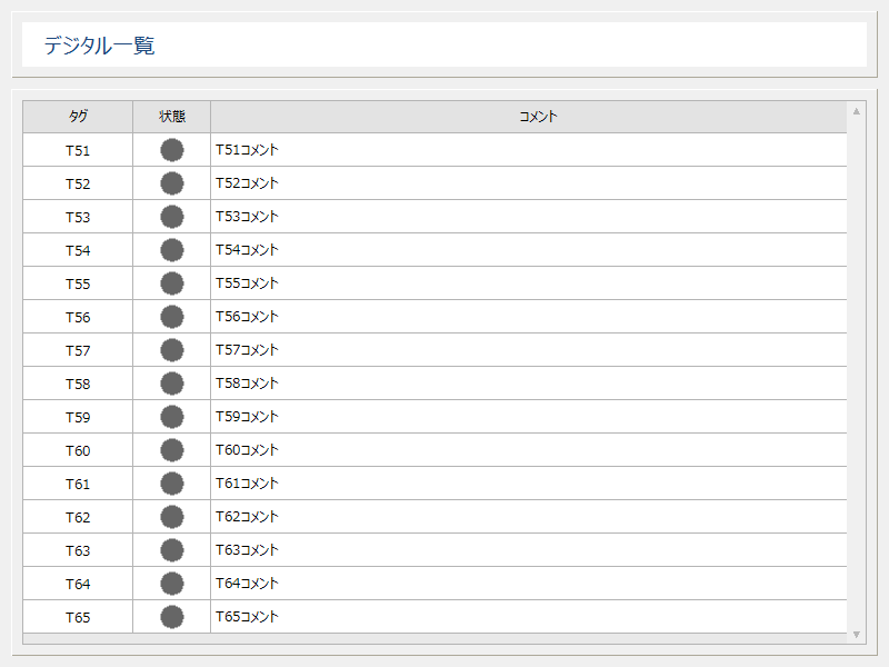
Currently, the value of each tag is FALSE (Off), so the lamp display is gray. Try changing the value to any value in the tag monitor of Panel Server.
As a test, set T51 to TRUE.
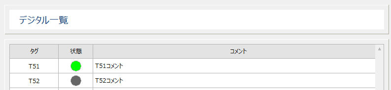
It's OK if the
T51 status light turns green.