overview
This is a setting example for connecting to the NJ/NX1P/NX1 series via Ethernet. Since the NJ/NX1P/NX1 series has a built-in Ethernet port attached to the CPU, this example uses the built-in port for connection.
In this connection example, communication will be performed using the auto-generation method.
Model used
item |
Model etc. |
PLC |
NJ501-1500 Ver1.00 |
Communication Unit |
CPU Attached Port |
Configuration environment
item |
environment |
OS |
Windows7 Professional 64Bit |
tool |
Sysmac Studio Ver1.00 |
Configuration details
item |
setting |
Setting items |
Configuration Example |
PLC side settings |
Setting with switches and tools |
IP address |
192.168.0.100 |
Subnet mask |
255.255.255.0 |
||
Port number |
9600 |
||
FINS Node |
100 (the end of the IP address) |
||
IP address conversion method |
Automatic generation method |
||
PC settings |
Unit Settings |
IP address |
192.168.0.1 |
Port number |
Automatic |
||
Folder and communication test settings |
Source Network Number |
000 |
|
Source Node |
999 |
||
Destination network number |
000 |
||
Destination Node |
999 |
* Most of the settings on the computer will be adjusted to match the settings on the unit.
|
In this connection example, the IP address conversion method is the "Automatic generation method". The "Automatic generation method" cannot be used with Ethernet communication cards older than ETN21. If you are using ETN01 or similar, please refer to "Connection example [CS1 series/IP address table method]". |
PLC side settings
Configure the "NJ501". The settings are done using the switch on the front and "Sysmac Studio".
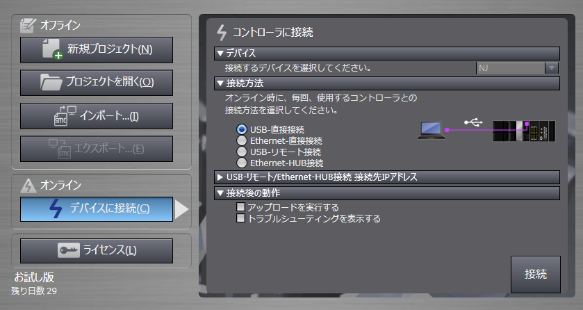
1.Connect to the device
Please select the appropriate connection method for your environment.
2.Once the connection is complete, a message will appear
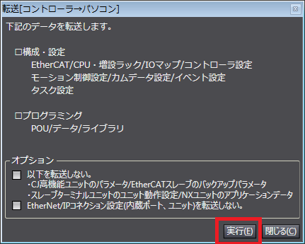
3.If the settings have already been configured on the PLC side, transfer the configuration information on the PLC side to the PC from the menu "Controller" - "Transfer" - "Transfer [Controller to PC]".
Please select the content to be transferred according to your environment.
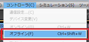
4.Select "Controller" - "Offline" from the menu to set the connection offline.
5.From the tree, open "Controller Settings" - "Action Settings" - "Built-in Ethernet/IP Port Settings"
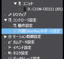
|
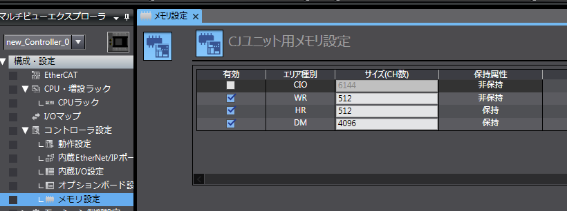
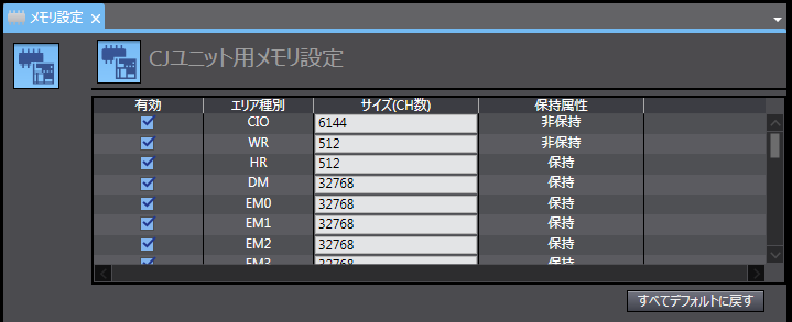
For NX1P/NX1, you must enable the device to be used in the memory settings for the CJ Unit in "Controller Settings" - "Memory Settings".
Setting example (NX1P)
Setting example (NX1)
|
6.Set the IP address in "Built-in Ethernet Port Settings" in "TCP/IP" as follows:
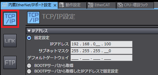
setting |
Setting contents |
IP address |
192.168.0.100 |
Subnet mask |
255.255.255.0 (Please set according to your environment) |
7.Set the following in "FINS Settings"
* If you select a method other than "Automatic generation" for the node address conversion method, please also configure the other settings.
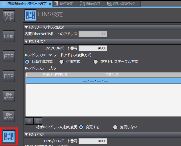
setting |
Setting contents |
FINS Node Address |
100 (The last value of the IP address you set will be automatically assigned.) |
FINS/UDP Port number |
9600 |
FINS Node address conversion method |
Automatic generation method |
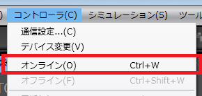
8.Select "Controller" - "Online" from the menu and make the connection online.
9.Write the settings from the menu "Controller" - "Transfer" - "Transfer [PC to Controller]"
Please select the content to be transferred according to your environment.
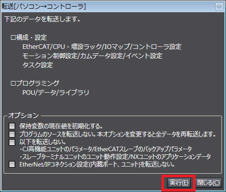
10.Verify that the message "Successfully completed" is displayed.
PC settings
Use the Server application to connect to the PLC for which you have set up communications.
1.Right-click "Application" - "Driver" in the tree and select Add Driver.
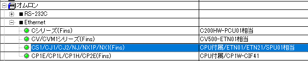
2.Select the following units from the displayed driver list and add them:
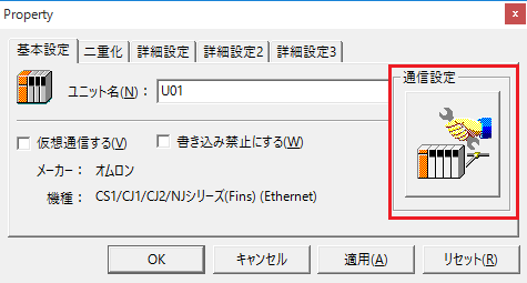
3.Open the properties of the added unit (U01) and click Communication Settings.
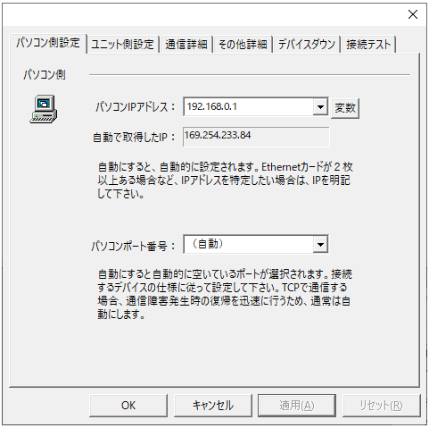
4.Configure the following in "PC Settings"
setting |
Setting contents |
Computer IP address |
192.168.0.1 |
Computer port number |
Automatic |
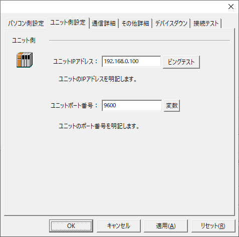
5.Set the following in "Unit side settings"
setting |
Setting contents |
Unit IP Address |
192.168.0.100 |
Unit Port Number |
9600 |
6.Select "Ping Test" to check if the ping goes through normally.
If you see a message like "Ping test is success~", the test was successful.
7.Select the protocol in "Communication Details"
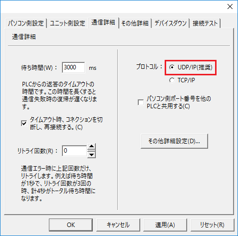
setting |
Setting contents |
protocol |
UDP (recommended) |
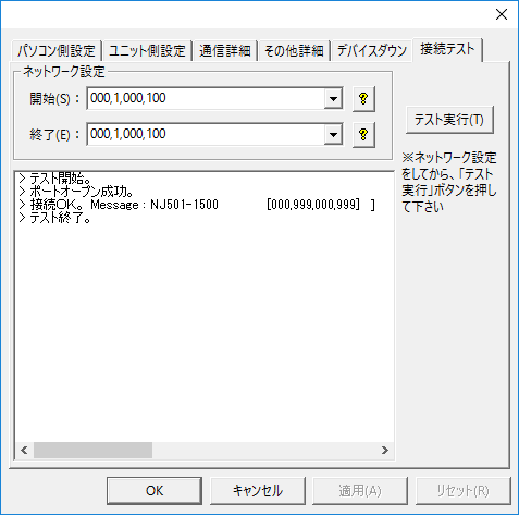
8.Perform a connection test to check the connection
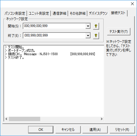
If a message such as "Connection OK" is displayed, the connection is confirmed to be OK.
|
When testing the connection and setting up the folder, do not forget to specify the node (network settings).
•Source/Destination Network Number: Please specify the network number. Specifying 000 will indicate your own network. •The source/destination node sets the node. If you specify 999, the last part of the IP address will be the node.
If you connect using the settings in this example, you can also connect by specifying "000,1,000,100".
|