About the connection example
Please see below for an example of connection settings for this driver.
Applicable models etc. |
explanation |
This is an example of Ethernet connection settings with the CS1E series (Connection method: Auto-generation method).
|
|
This is an example of an Ethernet connection setting with the CS1E series (Connection method: IP address table method).
|
|
Connection example [CJ2M series/automatic generation method] |
This is an example of an Ethernet connection setting using the CPU's built-in port of a CJ2M series (Connection method: Auto-generation method).
|
Connection example [NJ/NX1P/NX1 series/Automatic generation method] |
This is an example of an Ethernet connection setting using the CPU built-in port of the NJ/NX1P/NX1 series (Connection method: Auto-generation method).
|
For information on connection methods, please refer to "About connection methods" on this page.
Device List
The compatible devices are as follows (see here for how to view the device list).
device |
keyword |
Start address |
explanation |
unit |
reading |
Writing |
Input/Output Relays |
IO |
000000 |
Decimal number 4 digits (CH) + 2 digits (00 to 15) |
bit |
○ |
○ |
Internal Auxiliary Relay |
WR |
00000 |
Decimal number 3 digits (CH) + 2 digits (00 to 15) |
bit |
○ |
○ |
Holding Relay |
HR |
00000 |
Decimal number 3 digits (CH) + 2 digits (00 to 15) |
bit |
○ |
○ |
Auxiliary Memory Relay |
AR |
00000 |
Decimal number 3 digits (CH) + 2 digits (00 to 15) |
bit |
○ |
○ |
Timer Up Flag |
TS |
0000 |
Decimal |
bit |
○ |
× |
Counter Up Flag |
CS |
0000 |
Decimal |
bit |
○ |
× |
Timer current value |
TN |
0000 |
Decimal |
word |
○ |
● |
Counter current value |
CN |
0000 |
Decimal |
word |
○ |
● |
Data Memory |
DM |
00000 |
Decimal |
word |
○ |
○ |
Extended memory (current) |
EM |
00000 |
Decimal |
word |
○ |
● |
Extended memory (bank designation) |
EB |
000000 |
Hexadecimal 1 digit (bank) + 5 digits (address) |
word |
○ |
○ |
Task flags (bits) |
TKB |
0000 |
Decimal |
word |
○ |
× |
Task flags (status) |
TKS |
0000 |
Decimal |
word |
○ |
× |
Index Register |
IR |
00 |
Decimal |
word |
○ |
● |
Data Register |
DR |
00 |
Decimal |
word |
○ |
● |
|
The NX1P only supports the following devices:
Input/Output Relay (IO) ・Internal auxiliary relay (WR) ・Holding relay (HR) ・Data memory (DM)
It is not compatible with other devices. |
|
The NX1 only supports the following devices:
Input/Output Relay (IO) ・Internal auxiliary relay (WR) ・Holding relay (HR) ・Data memory (DM) ・Expanded memory (EM/EB)
It is not compatible with other devices. |
About duplicate port numbers
When using an Ethernet communications card such as ETN01 and UDP to connect to multiple PLCs from one PC, it is necessary to avoid duplication of port numbers on the PC side.
There are two ways to do this. If you have no other reason, we recommend using method 1.
Method 1
Change the port number of each PLC (default 9600) so that they are not duplicated.
Method 2
In the Server application settings, check "Share the PC port number with other PLCs" for all PLC units that have the same PC port number.
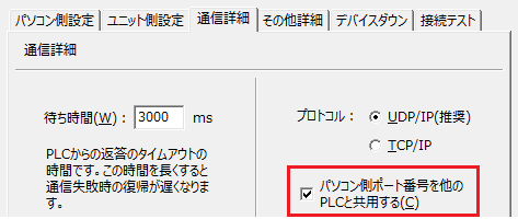
However, if you are using an Ethernet communications card of ETN21 or later and UDP to connect to multiple PLCs from one PC, do not check the "Share PC port number with other PLCs" option above, and set it as follows:
・Select UDP connection
・Select the automatic generation method (dynamic) in the CX-Programer settings.
- Set the source node number uniquely in the network settings of the unit folder so that there are no duplicates
- Set the port number on the PC side of the unit properties to automatic.
For details on the settings, please refer to the connection example "Connection example [CS1 series/Automatic generation method]".
Points to note when connecting to TCP/IP
When using TCP communication with an Omron PLC, if some kind of communication failure occurs, PLC may hold the connection and the PC may not be able to reconnect for a while. The CX-Programer setting "TCP/IP keep-alive" is set to 120 minutes by default, but with this setting, it may not be possible to reconnect for 120 minutes after some kind of communication failure.
Even if you set "TCP/IP keep-alive" to the minimum setting of 1, you will still have to wait about 10 minutes. If this specification is a problem, please select communication via UDP.
About setting connection parameters
When connecting to PLCEthernet, the network settings must be as follows:
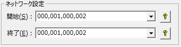
item |
explanation |
1 |
Source network number (0 is your own network) (specify in the range 000 to 127, decimal) |
2 |
Source node (IP suffix when 999) (specify in the range 001 to 999, decimal) |
3 |
Destination network number (0 is your own network) (specify in the range 000 to 127, decimal) |
4 |
Destination node (IP suffix when 999) (specify in the range 001 to 999, decimal) |
The default settings (settings in "11-2 FINS Network Settings" in "Chapter 11 Unit Settings" of the "SYSMAC CS/CJ Series SYSMAC SPU Basic Software" (WS02-SPTC1-V1)) will be as follows.
Source Network Address |
: 02 |
Source Node |
: The last number of the IP address (for example, 192.168.1.12, it is 12) |
Destination network address |
: 04 |
Destination Node |
: 02 |
If you are using your own network address and the last number of the IP address as the node, leave it as the default, "000,999,000,999." 000 represents your own network address, and 999 represents the end of the IP.
When connecting to an Omron PLC via Ethernet, you can select from several connection configurations.
Automatic generation method
In the dynamic method, you can dynamically change the information in the internal table once it has been created. If you select this method, you will be able to freely set the IP address and port number. However, if you are using the Ethernet unit, this is only available from ETN21 onwards.
IP address table method
Create the destination IP and node information for the PLC in the internal table in advance. When connecting with UDP, the PC port number must be set to the same number as the PLC port number. Also, since the connected client depends on the settings in the internal table on the PLC side, you will not be able to freely change the IP address or port number.
Combined Use
The combined method uses both the IP address table method and the automatic generation method (dynamic). If the IP address table is referenced and there is no corresponding setting, the IP address is calculated using the automatic generation method (dynamic setting).
|
For details on the connection method, refer to the user's manual for the PLC and Ethernet unit being used. |
Ethernet port attached to the CPU of the NX1 series
Some NX1 series CPUs have multiple Ethernet/IP ports. When communicating using an Ethernet/IP port attached to the CPU, it is necessary to connect to a port that supports the FINS protocol.
For example, for NX102-1100, use Ethernet/IP port 2. Since the FINS protocol cannot be used with Ethernet/IP port 1, a response error will occur if you connect to it.
Please refer to your PLC manual for information on which ports you should actually use.