Alarm master reference settings
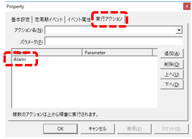
Alarm serverThe action setting screen has a setting section where you can specify the reference destination for the alarm master.
|
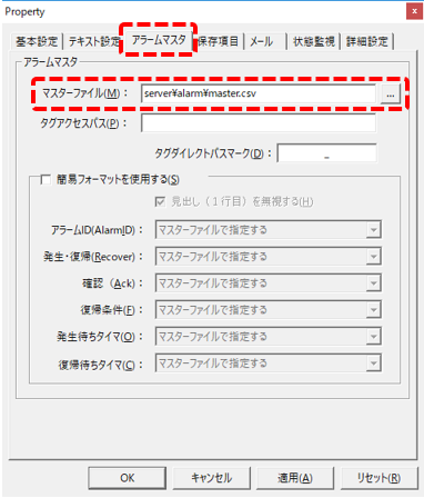
The image on the left is the setting screen for the "Alarm" action included in the sample of the Alarm Summary Screen Library.
The reference destination "server\alarm\master.csv" is set in advance.
*In this case, the folder containing the server configuration file (server.txt) will be recognized as the current folder.
|
Alarm Master Format
The rules for writing alarm masters are as follows:
•Line 1: Title line
•Line 2: Field definition
•From the third line onwards: Alarm settings (definition of occurrence conditions, message, etc.)
(Example)
Alarm ID, occurrence and recovery, confirmation, occurrence condition, comment 0, comment 1, alarm level [ALARMID],[RECOVER],[ACK],[ONCONDITION],[CM0],[CM1],[CM2] ALARM-001,y,y,U01.F01.M0000,Sample alarm 1,Minor fault,1 ALARM-002,y,y,U01.F01.M0001,Sample alarm 2,Medium fault,2 ALARM-003,y,y,U01.F01.D0000 > 100,Sample alarm 4,Major fault,3 ALARM-004,y,y,U01.F01.M0003 && U01.F01.M0004,Test Alarm 5,Medium Fault,2 |
First line |
Title line. You can freely write the column headings of the alarm master, separated by commas.
For example, write it as follows:
Alarm ID, occurrence and recovery, confirmation, occurrence condition, comment 0, comment 1, alarm level
|
Second line |
Specify the type of each field to be defined in the alarm master. Specify which field is defined in which column, separated by commas.
For example, the alarm master for alarm monitoring in the standard project is written as follows:
[ALARMID],[RECOVER],[ACK],[ONCONDITION],[CM0],[CM1],[CM2]
Here, the format enclosed in square brackets, such as [ALARMID] or [ACK], represents a field. In the above example, the first column is interpreted as the alarm ID, the second column as whether the alarm occurred and was restored, the third column as whether the alarm was acknowledged, the fourth column as the occurrence condition, and so on.
In addition to the fields that are predefined in the standard project, various other types of fields are available. For details on the fields that can be defined in the alarm master, see "Alarm Master Format".
|
Third line |
Alarm settings. Define the information for each alarm in the order of the fields specified on the second line, separated by commas.
For example, write it as follows:
ALARM-001,y,y,U01.F01.M0000,Sample alarm 1,Minor fault,1 ALARM-002,y,y,U01.F01.M0001,Sample alarm 2,Medium fault,2 ALARM-003,y,y,U01.F01.D0000 > 100,Sample alarm 4,Major fault,3 ALARM-004,y,y,U01.F01.M0003 && U01.F01.M0004,Test Alarm 5,Medium Fault,2 : : :
|
Alarm retention period
Alarm serverYou can specify the retention period in days from the action settings screen.
|
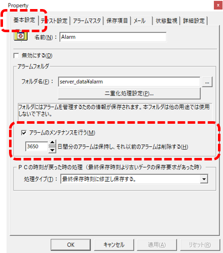
In the Basic Settings tab, check "Perform alarm maintenance" and specify the storage period.
In the standard framework, the default is 3650 days (approximately 10 years).
If you want to change the storage period, please change the settings on the left.
|
About Alarm server actions and Periodic event
The Alarm server action must be configured to call from Periodic event.
For example, in the case of the alarm function of the standard framework, Periodic event events with a one-second period named "Alarm" and "Event" are registered, and the Alarm server actions "Alarm" and "Event" are configured to be called periodically, respectively.
(Example of execution action for Periodic event "Alarm")
|
Please note that this Periodic event is not the period for detecting alarms.
Alarms are detected whenever the tag value changes, based on the tag update cycle. Detected alarms are temporarily stored in a message queue inside Alarm server, and when called from the above Periodic event, the message queue is checked, and if an alarm exists in the queue, it is written to disk and the client is notified of the alarm.
|